100
Sirius-PJ1Training
Slide 100
Multi Media (MM) Processing Unit
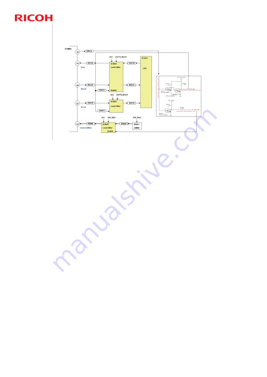
Audio Output
Peripheral circuits of Q9001,
Q9003, and Q9013
The audio output from the MM board functions when audio is to be output in the
video playback.
The 24MHz-Clock signal from the crystal oscillator (X9601) is output to the MAIN
board via POMM2 (70-pin connector). This 24MHz-Clock signal is input to the
audio DAC (IC5202) of the MAIN board. The audio DAC outputs BCLK (Bit
Clock) and WCLK (Word Clock) based on the 24MHz-Clock signal. This signal is
input to the CPU (IC9201) via POMM2 (70-pin connector). The CPU (IC9201)
outputs the audio data which is synchronized with BCLK (Bit Clock) and
WCLK(Word Clock), then input to the audio DAC on the MAIN board. The analog
audio signal which is converted to a digital signal is input to the audio processor
IC (5401). The signal level of 24MHz-Clock/BCLK (Bit Clock) and WCLK (Word
Clock)/audio data differ in the MM board side and the MAIN board side, therefore
level conversion is processed with IC9003, IC9004, and IC9007. IC9003,
IC9004, and IC9007 are controlled by the BUF_EN signal (enable signal).


