background image

1. OVERALL MACHINE INFORMATION

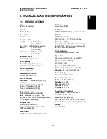
1.1. SPECIFICATIONS

Type
Desktop transceiver

Circuit
PSTN, PABX

Connection
Direct couple

Document Size
Length: 

105 - 1200 mm 
[4.13 - 47.2 ins]

Up to 100 m [328 ft] after adjustment
Width: 

148 - 216 mm 
[5.8 - 8.5 ins]

Thickness: 

0.05 to 0.15 mm 
[2 to 6 mils] 

Document Feed
Automatic feed, face down

ADF Capacity
20 sheets (using 20 lb paper)
30 sheets (using 80 g/m

2

 paper)

Scanning Method
Flat bed, with CCD

Maximum Scan Width
216 mm [8.5 ins] 

±

 1%

Scan Resolution
Main scan:

8 dots/mm [203 dpi]

Sub scan:
Standard - 3.85 lines/mm [98 lpi]
Detail - 7.7 lines/mm [196 lpi]
Fine - 15.4 lines/mm [392 lpi]

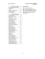
Memory Capacity
ECM:
 128 kbytes (double buffer)
SAF:   256 kbytes (14 pages), with 
optional  extra 1 Mbyte or 2 Mbytes (max 71
or 128 pages respectively)

Compression
MH, MR, EFC, MMR, SSC
Storage to SAF memory for tx: MH
MMR only with ECM

Modulation
V.29 (QAM), V.27ter (PHM), V.21 (FM)

Protocol
Group 3 with ECM

Data Rate
9600/7200/4800/2400 bps; automatic fallback

I/O Rate
With ECM: 0 ms/line
Without ECM: 5, 10, 20, or 40 ms/line

Transmission Time
10 s at 9600 bps (G3 ECM using memory)
for a CCITT # 1 test document (Slerexe let-
ter) using standard resolution

Printing System
Thermal printing, automatic cutter

Paper Size
216 mm (A4) x 100 m [8.5 ins x 328 ft]

Maximum Printout Width
210 mm [8.3 ins]

Maximum Printer Resolution
Main scan:
 8 dots per mm [203 dpi]
Sub scan: 15.4 lines/mm [392 lpi]

Power Supply
115 

±

 20 Vac, 60 

±

 1 Hz

Power Consumption
(Without Optional Kits)
Standby:
 13 

±

 5 W

Transmit: 29 

±

 5 W

Receive: 22 

±

 5 W

Copying: 41 

±

 7 W

Operating Environment
Temperature:
 17 - 28 °C [63 - 82 °F]
Humidity: 30 - 85 %Rh

Dimensions (W x D x H)
325 x 388 x 174 mm [12.8 x 15.3 x 6.9 ins]
Excluding handset, trays, and optional units

Weight
10 kg [22 lbs]

1

OVERALL MACHINE INFORMATION

November 30th, 1991

SPECIFICATIONS

1-1

Summary of Contents for FAX500

Page 1: ...FAX550 SERVICE MANUAL...

Page 2: ...ON The danger of explosion exists if a battery of this type is incorrectly replaced Replace only with the same or an equivalent type recommended by the manufacturer Discard used batteries in accordanc...

Page 3: ...1 5 1 Transmission 1 10 1 5 2 Reception 1 10 1 6 POWER DISTRIBUTION 1 11 1 6 1 Distribution Diagram 1 11 1 6 2 Memory Back up Circuit 1 12 2 DETAILED SECTION DESCRIPTIONS 2 1 SCANNER 2 1 2 1 1 Mechan...

Page 4: ...4 1 6 RAM Display Rewrite Function 95 4 3 4 1 7 RAM Dump Function 95 4 3 4 1 8 NCU Parameters Function 96 4 4 4 1 9 ADF Test Function 97 4 4 4 1 10 Xenon Lamp Test Function 97 4 5 4 1 11 DTMF Tone Te...

Page 5: ...ers 5 1 5 2 SCANNER 5 2 5 2 1 ADF Clutch and Pick up and Feed Rollers 5 2 5 2 2 Separation Roller 5 3 5 2 3 Tx Motor 5 4 5 2 4 Timing Belt Tension Adjustments 5 4 5 2 5 Xenon Lamp 5 5 5 2 6 Xenon Lamp...

Page 6: ...UBLESHOOTING 6 1 6 1 1 Received Copies 6 1 6 1 2 Copies made in Copy Mode 6 1 6 2 MECHANICAL PROBLEMS 6 2 6 2 1 ADF Scanner 6 2 6 2 2 Printer 6 5 6 3 ERROR CODES 6 7 6 4 ELECTRICAL COMPONENT DEFECTS 6...

Page 7: ...to SAF memory for tx MH MMR only with ECM Modulation V 29 QAM V 27ter PHM V 21 FM Protocol Group 3 with ECM Data Rate 9600 7200 4800 2400 bps automatic fallback I O Rate With ECM 0 ms line Without ECM...

Page 8: ...er broadcaster X AI Redial O Alternative Destination O Answering machine O Authorized Reception O Auto answer delay time X Auto dialing pulse or DTMF O Auto Document O Automatic Voice Message X Auto n...

Page 9: ...Language Selection O LCD contrast control Service Memory Lock A Memory Lock ID A Modifying a memory file X Multi Sort Document Reception X Multicopy mode X Night Timer X Own telephone number O Printi...

Page 10: ...Operation panel test O Printer mechanism test X Printer test patterns O Programmable attenuation X Protocol dump list O RAM display rewrite O RAM dump O Ringer test X Scanner lamp test O Scanner mecha...

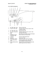
Page 11: ...Device This converts the light reflected from the document into an analog video signal 11 Thermal Paper Roll Thermal paper for printing 12 Shading Plate Allows more light through from the ends of the...

Page 12: ...ive Gear Drive the document feed roller which feeds the document into the scanner 6 Tx Motor Drives the ADF and scanner 7 Rx Motor Drives the printer 8 Printer Drive Gears Transfer Rx motor drive to t...

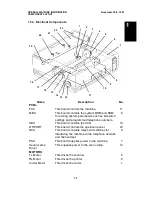
Page 13: ...ls the operation panel 23 NCU This board contains relays and switches for interfacing the machine to the telephone network and the handset 4 PSU This board supplies power to the machine 7 Xenon Lamp D...

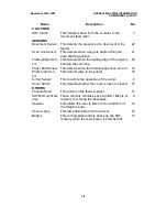
Page 14: ...out 16 Printer Jam Sen sor This detects jams in the printer 18 Cutter Sensor This monitors the operation of the cutter 2 Cover Switch This detects whether the cover is open or closed 15 OTHERS Thermal...

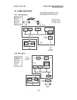
Page 15: ...is a separate analog modem chip called the Modem AFE which does the rest of the modem operations DATA AND ADDRESS BUS Scanner Sensors CONTROL SIGNALS Scanner and Printer Drive Components and Sensors...

Page 16: ...mp FCU CPU Modem Analog Modem Digital MODEM AFE There is no pro grammable resis tor in this model Reference Group 3 Facsimile Manual section 1 3 1 Line Buffer FIFO RAM SAF Memory ECM Memory Modem Anal...

Page 17: ...cpu when a ringing signal is de tected or when the user presses the Start or Copy key It is not inter rupted if the cover switch is opened however printing stops and the document is fed out In some do...

Page 18: ...mory and the real time clock for 1 hour When the main power is switched on the 24V supply charges the battery If there is data in the SAF the battery also backs up the real time clock to preserve the...

Page 19: ...There is no document width detector The scanner contains a xenon lamp There is no shutter mechanism Reference Group 3 Facsimile Manual section 2 1 ADF Clutch Scan Line Sensor Document Sensor Separati...

Page 20: ...its data at 15 4 lines mm If the other terminal cannot receive at this resolution the tx motor feeds the paper at 7 7 lines mm and the data is transmitted using Detail resolution Jam Conditions The cp...

Page 21: ...e Process Halftone Error Diffusion Halftone Process Corrected Data from the Auto Shading Circuit Gamma Correction MTF Reference Group 3 Facsimile Manual section 2 3 Amplifier A DC Filter Peak Hold FEE...

Page 22: ...ion Standard Each received line is printed 4 times Detail Each received line is printed twice Fine Each received line is printed once One way Clutch Feed out Roller Platen Roller Rx Motor Reference Gr...

Page 23: ...after the end of the feed out procedure for the last page of a print run 2 Cutting The cutter mechanism is exactly as described in section 3 6 of the Group 3 Facsimile Manual 3 Cutter Jam Detection A...

Page 24: ...ile Manual except that when printing a line blocks 0 and 1 are printed together then blocks 2 and 3 are printed together The data are printed as explained in section 3 5 3 of the Group 3 Facsimile Man...

Page 25: ...mponents and Sensors RAM ROM Thermal Head Video Processing Memory Video Processor SBU CCD Operation Panel PSU I O Port CPU MBU FCU RS 232C Interface Drivers SAF Memory ECM Memory Memory Back up Contro...

Page 26: ...r monitoring including A D conversion where necessary Tone detection Thermal head control Tx Rx cutter motor drive control Operation panel control 3 Modem Analog Front End Modem AFE Modem analog opera...

Page 27: ...PSRAM for parameter storage line buffer FIFO SAF memory administration The SRAM is backed up by the battery on the MBU DATA AND ADDRESS BUS System ROM System RAM To From FCU To From FCU MBU Memory Ba...

Page 28: ...anel Controller Serial Interface To From FCU Output from the Scanner Sensors Operation Panel Controller 12V 12V Emitter Follower Inverter Amplifier SBU Drivers CCD Analog Video To the FCU Drive Clocks...

Page 29: ...standby position for Auto Receive Fax Mode FG Protection Circuit TIP RING Di Switch Tx Rx Data To From FCU Line Current Detector To FCU Auto Mode Relay To FCU 24V From FCU T1 R1 T2 R2 Oh Relay Answer...

Page 30: ...ge Take care because it may be hot 3 Put back the PSU and switch the machine on If the machine does not op erate change the PSU LIVE NEUTRAL GROUND Surge Prevention Arrestor Main Switch Noise Filter S...

Page 31: ...3 INSTALLATION 3 1 CONNECTING UP THE MACHINE LINE 3 INSTALLATION November 30th 1991 CONNECTING UP THE MACHINE 3 1...

Page 32: ...have to be changed to match line conditions or user requirements Have you programmed the serial number Function 98 section 4 1 18 The user should program the following items after installation Telepho...

Page 33: ...bit switch Example Display bit switch 3 x 3 DEFAULT 0000 0000 BITSW03 0000 0000 4 Adjust the bit switch Example To change the value of bit 7 press 7 DEFAULT 0000 0000 BITSW03 1000 0000 5 Either Adjust...

Page 34: ...sh Function 4 1 4 Service Monitor Function 93 1 Function 5 1 9 9 1 then immediately Yes FUNCTION Y 9 SERVICE FUNCTIONS 2 9 3 Yes ERROR CODE 1 01 JAN 01 17 30 3 No Start 4 1 5 Protocol Dump Function 94...

Page 35: ...RESS 20202 DATA 80 Note If you wish to move the cursor press 6 Either View more addresses go to step 4 Finish Yes Function 4 1 7 RAM Dump Function 95 1 Function 5 1 9 9 1 then immediately Yes FUNCTION...

Page 36: ...h Function Note Parameter 00 is the Country Code and Parameter 01 is the Tx Level if the Tx level should be 9 dB input 9 Refer to section 4 3 for full details on NCU parameters 4 1 9 ADF Test Function...

Page 37: ...Function 5 1 9 9 1 then immediately Yes FUNCTION Y 9 SERVICE FUNCTIONS 2 9 7 Yes SCN 1 DT 2 PL 3 LD 4 MDM 5 RI 6 CK 7 SN 8 3 2 DTMF TEST DUAL 1 SINGLE 2 4 Either Test dual tones 1 Go to step 5 Test s...

Page 38: ...Printer Test Patterns Function 97 1 Function 5 1 9 9 1 then immediately Yes FUNCTION Y 9 SERVICE FUNCTIONS 2 9 7 Yes SCN 1 DT 2 PL 3 LD 4 MDM 5 RI 6 CK 7 SN 8 3 3 PATTERN PRINT KPAD 1 7 4 Press a key...

Page 39: ...shown opposite 9600 1 7200 2 4800 3 2400 4 300 5 Press the required key Example Test the 9600 bps carrier 1 Start 6 To stop the test Stop 7 Either Test another tone Go to step 5 Finish Function 8 The...

Page 40: ...nitialization Function 97 1 Function 5 1 9 9 1 then immediately Yes FUNCTION Y 9 SERVICE FUNCTIONS 2 9 7 Yes SCN 1 DT 2 PL 3 LD 4 MDM 5 RI 6 CK 7 SN 8 3 8 NOW SETTING SENSORS The reflective photosenso...

Page 41: ...6 To correct a mistake No 4 If the display is correct Yes 4 1 19 Pulse Width Function 99 1 Function 5 1 9 9 1 them immediately Yes FUNCTION Y 9 SERVICE FUNCTIONS 2 9 9 Yes PULSE WIDTH HEAD 0 30MS A 3...

Page 42: ...eturned to standby mode Restricted Access is reimposed immediately 4 1 21 Printing all Memory Files Function 24 First set bit 5 of bit switch 01 to 1 1 Function 2 3 Yes or Function 2 4 Yes FILE NO 2 P...

Page 43: ...for use when it is necessary to clear the SAF as fewer RAMs will need reprogramming 3 Memory file forwarding 1 Forward the files Use this if the printer does not work but the user wishes to print the...

Page 44: ...st Use these bit switches to adjust the brightness of the LCD on the operation panel 3 4 Memory read write by RDS Bit 4 3 Setting 0 0 Always enabled 0 1 User selectable 1 0 User selectable 1 1 Always...

Page 45: ...stored for polling transmission will be erased immediately after polling 1 This allows the user to keep messages in memory to be polled by more than one station 2 Inclusion of communications on the T...

Page 46: ...he post message command As 10 or 20 or 40 good lines cause the count to decrement RTN will only occur in bad conditions 3 4 Burst error threshold Bit 4 3 Threshold 0 0 3 6 12 0 1 4 8 16 1 0 5 10 20 1...

Page 47: ...not have to wait out the CCITT T1 time before hanging up if the line is busy 5 Not used Do not change the factory setting 6 7 PSTN access method through PABX Bit 7 6 Method 0 0 No PABX 0 1 Loop Start...

Page 48: ...on 6 Post message response timing rx 0 After feed out 1 When the leading edge reaches the printer jam sensor 0 Data cannot be stored in the SAF during reception if the memory is full so if this bit i...

Page 49: ...t work for manual dialing 1 0 The same as above except that only the last 4 digits are compared 1 1 The machine will not transmit if the other end does not identify itself with an RTI or CSI 0 0 Nothi...

Page 50: ...llback occurs frequently 7 Not used Do not change the factory setting Bit Switch 0B Reception FUNCTION COMMENTS 0 Closed network reception 0 Disabled 1 Enabled 1 Reception will not go ahead if the ID...

Page 51: ...mit an RTI or CSI the call will be rejected and the machine will send DCN 6 Not used Do not change the factory settings 7 Bit switches 0F to 1F are not used Do not change any of the factory settings F...

Page 52: ...rrent is not detected if 413C contains FF 413D Line current wait time 413E Line current drop detect time 413F PSTN dial tone upper frequency limit HIGH Hz BCD See Note 2 4140 PSTN dial tone upper freq...

Page 53: ...is FF detection is disabled See Note 2 4158 PABX busy tone upper frequency limit LOW See Note 2 4159 PABX busy tone lower frequency limit HIGH 415A PABX busy tone lower frequency limit LOW 415B Busy t...

Page 54: ...r frequency limit LOW 4170 Country dial tone lower frequency limit HIGH 4171 Country dial tone lower frequency limit LOW 4172 Country dial tone detection time 20 ms If 4172 contains FF the machine pau...

Page 55: ...ction 96 parameter 08 4189 Ringing signal detection reset time 40 ms Function 96 parameter 09 418A Time between opening or closing the Ds relay and opening the Di relay Europe Asia only 1 ms See Note...

Page 56: ...ers addresses 418A to 418F are the values for 10 pps If 20 pps is used the machine automatically compensates 4 The first ring may not be detected until 1 to 2 5 wavelengths after the time specified by...

Page 57: ...m the actual hexadeci mal contents of the RAM address if there is no H after the value Some RAMs must be programmed in BCD See the NCU parameter definitions for details Address 4147 4155 416D 4176 Val...

Page 58: ...e 2 41D4 Off time range 2 Country Frequency Hz Cadence Europe ver sion defaults 430 0B77 is stored in RAM 0 4 s on 0 2 s off RAM On times 14 H Off times 0A H Asia version defaults 400 0AAB is stored i...

Page 59: ...ample Change the Parameters in Quick Dial 10 3 Function 3 2 Yes QUICK QUICK PRINT LIST 4 Press Quick Dial key 10 QUICK 10 Y N SET PARAMETER Note When selecting Speed Dial 10 with Function 33 1 0 on th...

Page 60: ...1 Enabled 0 The parameters in these three bytes will be ignored The current settings of the relevant bit switches NCU parameters and RAM addresses will be used 1 The parameters in these three bytes w...

Page 61: ...you wish to use a different T1 timer than the NCU parameter setting when sending to a particular terminal adjust this byte The T1 timer is the BCD value of this byte multi plied by 2 56 seconds Cauti...

Page 62: ...Black 1F All White 404D Contrast threshold Darken Hex code from 00 to 1F 00 All Black 1F All White 4053 Bit 0 Default resolution used for copy mode 0 As selected by the user 1 Fine 4054 Bit 0 Reductio...

Page 63: ...48 08 4053 00 4059 05 4049 02 4054 00 405D 24 Note When programming a RAM address you have to enter the bank number before the four digit RAM address In this model it is always 2 For example to progra...

Page 64: ...VERS 5 1 1 Top Cover A 5 1 2 Front B and Rear C Covers Caution Do not damage the cable at the front left side of the machine A 4 screws A A B C B 3 screws C 5 screws 1 washer A 5 REPLACEMENT AND ADJUS...

Page 65: ...d Hold the ADF clutch harness by the cord keep to move it away from gears and timing belts If you need to disassemble the one way clutch J see the diagram Caution Do not touch the rubber surface of th...

Page 66: ...t feed out area so that the pegs on the inside of the cover fit into the slots in the bracket above the document feed out area Caution Do not touch the rubber surface of the new rollers or document fe...

Page 67: ...Before replacing the ADF clutch cover adjust the timing belts as shown below 5 2 4 Timing Belt Tension Adjustments Loosen screw A adjust the belt then tighten screw A Loosen screw B adjust the belt t...

Page 68: ...before reassembly Clean the exposure glass with a soft cloth before putting it back Do not get fingerprints on the exposure glass After reassembly check the tension of the tx motor timing belts see s...

Page 69: ...ch Preparation 1 Remove the top cover see section 5 1 and the SBU cover see section 5 2 7 item A 2 Set the oscilloscope scale to 0 2 V unit vertical and 0 5 ms unit horizon tal 3 Connect the test lead...

Page 70: ...re glass white pressure plate or CCD may be dirty If the waveform is lower at the ends than in the middle the xenon lamp may be wearing out If the waveform has sharp peaks or dropouts the CCD may be d...

Page 71: ...securing screw 4 Reduction Rate Place the 8 line mm test pattern on the exposure glass Loosen the lens block securing screws A Move the lens block B back and forth until the signal has 8 or fewer cro...

Page 72: ...o VADJ pin 2 red wire and connect up the ground to pin 4 black wire Set the oscilloscope scales as follows Vertical CH1 0 2 V unit CH2 2 V unit Horizontal 2 s unit Gently tap the SBU until the wavefor...

Page 73: ...tioned and that the springs pushing the head against the platen roller are in position Reassembly Fit pin D into slot E at the front then fit pin F into slot G at the rear When replacing plate B fit t...

Page 74: ...pened a little more than usual Then remove the rear cover see section 5 1 Reassembly Clearance D must be 0 3 mm To adjust D loosen the screws that hold the cutter C and move the cutter back and forth...

Page 75: ...ed Reassembly The SAF memory has been erased The user must reprogram files for trans mission that were erased and must also contact the senders of messages that were received into memory and erased se...

Page 76: ...Make sure that the switch position is ON On the old MBU board turn the battery switch to OFF After reassembly Make a few copy and communication tests Program the thermal head pulse width Function 99 R...

Page 77: ...NCU B First remove the rear cover see section 5 1 Note Do not touch the PSU components They may be hot 5 4 5 Operation Panel B A B A B 4 screws B A A B 3 screws November 30th 1991 REPLACEMENT AND ADJU...

Page 78: ...Check the optical path Replace FCU or SBU Vertical lines Dirty mirror lens exposure glass or xenon lamp Error bit in CCD Clean with a soft cloth Replace SBU Uneven density Scan line out of position D...

Page 79: ...placed in the feeder Go to step 10 Go to step 6 6 Does the signal from the cover switch change when the cover is opened and closed If CLOSE COVER is not displayed when the cover is open change the FC...

Page 80: ...lean the rollers Metal soft cloth and alcohol Rubber soft cloth and water 2 Is the document feed path blocked Go to step 3 Remove any debris 3 Is the scanner mecha nism in good shape Go to step 4 Corr...

Page 81: ...Action if No Clean the rollers and guide plates Metal soft cloth and alcohol Rubber soft cloth and water Symptom Second page not fed in Check Action if Yes Action if No 1 Are the connections be tween...

Page 82: ...een the FCU NCU and telephone line loose Connect the cables properly Go to step 7 7 Does the FCU send the 24VD activation signal to the PSU when a ring ing signal is detected or when Copy is pressed R...

Page 83: ...or change in the correct way Change the FCU Replace the paper end sensor 8 Are the connections be tween the PSU FCU and the rx motor loose Connect the cables properly Go to step 9 9 Does the rx motor...

Page 84: ...4 CFR or FTT not received after modem training Check the line connection Check the NCU FCU connectors Try changing the tx level use NCU parameter 01 or a dedicated tx parameter for that address Replac...

Page 85: ...r a dedicated tx parameter for that address Replace the NCU or FCU 0 15 The other end does not have the confidential or transfer function Incompatible remote terminal Remote terminal memory full 0 16...

Page 86: ...ns between the sensors and the FCU Replace defective sensor operation panel board or FCU 1 17 Document jam in the feed out area 1 20 Printer jam paper did not reach the exit Clear any debris from the...

Page 87: ...Check the connections from the FCU to the NCU and line Replace the NCU or FCU 2 40 Thermal head driver irregularity Check the connections between the FCU thermal head and PSU Replace the FCU thermal...

Page 88: ...Check for a noisy line Adjust the tx levels of the communicating machines See code 6 05 6 10 Error frames still received at the other end after all communication attempts at 2400 bps G3 ECM Check for...

Page 89: ...mory filled up even though the mechanism was not defective Check the paper feed path and printer for errors if substitute reception has occurred Make room in the memory then ask the other end to resen...

Page 90: ...nsor The Replace Paper indicator lights even if paper is remaining The Replace Paper indicator does not light when the paper has run out Printer jam sensor No paper cycle at power up and CLEAR COPY is...

Reviews: