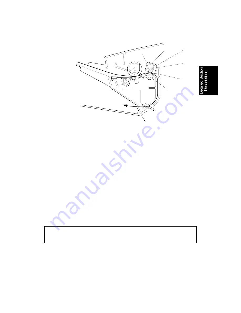
4. Image Scanning
The scanner consists of a contact image sensor (CIS) assembly [A] and a
scanner roller [B]. Inside the CIS are an exposure glass [C], a rod lens array
[D], an image sensor [E], and an LED array [F].
The image sensor consists of a row of 1728 photosensitive elements (216
mm width x 8 dots/mm). Light from the LED array is reflected from the docu-
ment and focused onto the image sensor by the rod lens array. Because of
the short optical path inside the CIS, the focal depth is much shorter than for
a CCD type scanner.
The white level adjustment is performed at the factory, then the white level is
stored in the FCU’s SRAM. The white level must be adjusted when the FCU
or the CIS is replaced, or the SRAM is cleared in the field.
The CIS scans the document one line at a time, and outputs an analog signal
for each line. The voltage from each element depends on the intensity of the
light reflected by the document onto the element; the intensity of the light de-
pends on the darkness of the area reflected.
Cross reference
White level adjustment: Service Tables and Procedures (chapter 4) - Function 10,
Shading Test
[A]
[B]
[C]
[D]
[E]
[F]
H528D515.wmf
July 30th, 1996
DETAILED SECTION DESCRIPTIONS
SCANNER
2-3


