Baby Lock BL9, Service Manual And Parts List
The Baby Lock BL9 is a versatile, high-quality sewing machine designed for everyday use. To ensure your machine’s optimal performance and longevity, make sure to have the Service Manual and Parts List on hand. This comprehensive manual is available for free download at manualshive.com, providing a convenient resource for troubleshooting and maintenance.
Share
Download


Reviews:
No comments
Related manuals for BL9

MICRO-IMAGECHECKER A200 Series
Brand: Panasonic Pages: 102
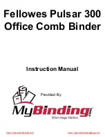
Pulsar E 300
Brand: Fellowes Pages: 7
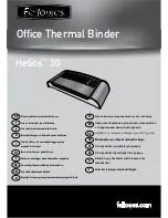
Helios 30
Brand: Fellowes Pages: 8
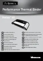
Helios 60
Brand: Fellowes Pages: 8

futura ce-100
Brand: Singer Pages: 100

CHARGER 2022 ABLT
Brand: NSS Pages: 16

EWF-E7152D
Brand: Elba Pages: 17

9900 - LEAFLET
Brand: ELNA Pages: 57

TFM 203
Brand: Gemsys Pages: 20

ULTRAFEED LS
Brand: Sailrite Pages: 38
202-082-204
Brand: ELNA Pages: 2

SFAX-500
Brand: Samyung Pages: 87

660A202
Brand: Singer Pages: 46

KORI NTO FB
Brand: N&W Global Vending Pages: 38

MH-486-5
Brand: JUKI Pages: 32

Alto FLOORTEC 550 P
Brand: Nilfisk-Advance Pages: 60

56314019
Brand: Nilfisk-Advance Pages: 82

1669U101
Brand: Singer Pages: 38


