Using the Debug Log
D017/D018/D019/D020/D084/D085 5-27
SM
Syste
m
Ma
in
te
na
n
ce
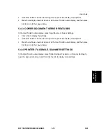
The initial settings are all zero.
These settings remain in effect until you change them. Be sure to check all the settings,
especially the settings for Keys 6 to 10. To switch off a key setting, enter a zero for that
key.
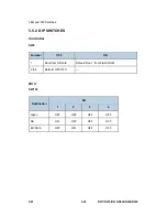
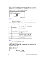
You can select any number of keys from 1 to 10 (or all) by entering the corresponding
4-digit numbers from the table.
You cannot mix settings for the groups (COPY, PRINTER, etc.) for 006 to 010. For
example, if you want to create a PRINTER debug log you must select the settings from
the 9 available selections for the "PRINTER" column only.
One area of the disk is reserved to store the debug log. The size of this area is limited to
4 MB.
5.6.2 RETRIEVING THE DEBUG LOG FROM THE HDD
1. Insert the SD card into service slot (slot 2) of the copier.
2. Enter the SP mode and execute SP5857 009 (Copy HDD to SD Card (Latest 4 MB) to
write the debugging data to the SD card.
3. Use a card reader to copy the file and send it for analysis to your local Ricoh
representative by email, or just send the SD card by mail.
5.6.3 RECORDING ERRORS MANUALLY
Since only SC errors and jams are recorded to the debug log automatically, for any other
errors that occur while the customer engineer is not on site, please instruct customers to
perform the following immediately after occurrence to save the debug data. Such problems
would include a controller or panel freeze.
To use this feature, the customer engineer must have previously switched on the
Save Debug Feature (SP5857-001) and selected the hard disk as the save
destination (SP5857-002).
1. When the error occurs, on the operation panel, press
(Clear Modes).
2. On the operation panel, enter "01" then hold down
for at least 3 seconds, until the
machine beeps. Then release the key. This saves the debug log to the hard disk for
later retrieval with an SD card by the service representatives.
3. Switch the machine off and on to resume operation.
4. The debug information for the error is saved on the hard disk so the service
representatives can retrieve it on their next visit by copying it from the HDD to an SD
card.
Summary of Contents for D017
Page 1: ...D017 D018 D019 D020 D084 D085 SERVICE MANUAL 003320MIU...
Page 2: ......
Page 3: ...D017 D018 D019 D020 D084 D085 SERVICE MANUAL...
Page 4: ......
Page 5: ...D017 D018 D019 D020 D084 D085 SERVICE MANUAL 003320MIU...
Page 6: ......
Page 8: ......
Page 10: ......
Page 12: ......
Page 26: ......
Page 33: ...PRODUCT INFORMATION REVISION HISTORY Page Date Added Updated New None...
Page 34: ......
Page 46: ......
Page 51: ...Copier Installation D017 D018 D019 D020 D084 D085 2 5 SM Installation...
Page 175: ...PREVENTIVE MAINTENANCE REVISION HISTORY Page Date Added Updated New None...
Page 176: ......
Page 179: ...REPLACEMENT AND ADJUSTMENT REVISION HISTORY Page Date Added Updated New None...
Page 180: ......
Page 206: ...Photoconductor Unit PCU SM 4 26 D017 D018 D019 D020 D084 D085 6 Drum E White clip x1 F...
Page 262: ......
Page 264: ......
Page 293: ...TROUBLESHOOTING REVISION HISTORY Page Date Added Updated New None...
Page 294: ......
Page 299: ...Self Diagnostic Mode D017 D018 D019 D020 D084 D085 6 5 SM Trouble Shooting...
Page 303: ...Image Problems D017 D018 D019 D020 D084 D085 6 9 SM Trouble Shooting...
Page 309: ...Image Problems D017 D018 D019 D020 D084 D085 6 15 SM Trouble Shooting...
Page 323: ...ENERGY SAVING REVISION HISTORY Page Date Added Updated New None...
Page 324: ......
Page 333: ...D017 D018 D019 D020 D084 D085 SERVICE MANUAL APPENDICES...
Page 334: ......
Page 337: ......
Page 339: ......
Page 363: ......
Page 364: ...APPENDIX PM TABLES APPENDIX 2 PM TABLES REVISION HISTORY Page Date Added Updated New None...
Page 365: ......
Page 373: ......
Page 375: ......
Page 433: ......
Page 672: ......
Page 674: ......
Page 694: ......
Page 696: ......
Page 698: ......
Page 724: ......
Page 728: ......
Page 731: ...Covers SM 3 B793 Booklet Finisher B793 3 Remove the upper left cover C...
Page 745: ...Folder SM 17 B793 Booklet Finisher B793 6 Remove a connector 7 7 Remove 2 screws 8...
Page 746: ...Folder B793 18 SM 8 Remove the staple tray 9 9 Remove the guide 10 2 screws...
Page 790: ......
Page 792: ......
Page 794: ......
Page 816: ......
Page 818: ......
Page 822: ......
Page 826: ......
Page 1043: ...ARDF DF3030 D366 ARDF DF3030 REVISION HISTORY Page Date Added Updated New None...
Page 1044: ......
Page 1048: ......
Page 1074: ......
Page 1075: ...1 BIN TRAY BN3030 D367 1 BIN TRAY BN3030 REVISION HISTORY Page Date Added Updated New None...
Page 1076: ......
Page 1078: ......
Page 1084: ......
Page 1085: ...BRIDGE UNIT BU3020 D368 BRIDGE UNIT BU3030 REVISION HISTORY Page Date Added Updated New None...
Page 1086: ......
Page 1088: ......
Page 1097: ...DUPLEX UNIT AD3000 D369 DUPLEX UNIT AD3000 REVISION HISTORY Page Date Added Updated New None...
Page 1098: ......
Page 1100: ......
Page 1104: ......
Page 1112: ...Electrical Component D369 8 SM 4 Duplex transport motor B x 2...
Page 1121: ...BYPASS TRAY BY3000 D370 BYPASS TRAY D370 REVISION HISTORY Page Date Added Updated New None...
Page 1122: ......
Page 1124: ......
Page 1126: ......
Page 1128: ...Tray D370 2 SM 2 Remove the pins A x 1 each 3 By pass tray B x 1...
Page 1133: ...Feed SM 7 D370 Bypass Tray BY3000 D370 6 Separation pad D spring x 1...
Page 1138: ......
Page 1140: ......
Page 1142: ......
Page 1148: ......
Page 1150: ......
Page 1156: ......
Page 1176: ...Overview D372 20 SM No What Happens sure that the stapler is at its home position...
Page 1220: ......
Page 1222: ......
Page 1224: ......
Page 1254: ...Scanner Service Tables D383 6 SM Compression Notch Assignment...
Page 1260: ......
Page 1262: ......
Page 1264: ......

