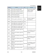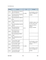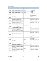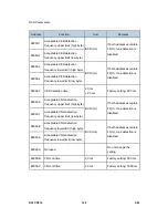
NCU Parameters
SM 173
D361/D510
D36
1/D5
10
Fax Op
tion
Ty
p
e
3350/3
351
Notes
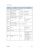
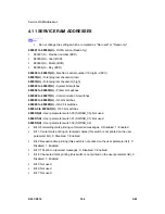
1. If a setting is not required, store FF in the address.
2. Italy and Belgium only
RAM address 68055E: the lower four bits have the following meaning.
Bit 2 - 1: International dial tone cadence detection enabled (Belgium)
Bit 1 - Not used
Bit 0 - 1: PSTN dial tone cadence detection enabled (Italy)
If bit 0 or bit 2 is set to 1, the functions of the following RAM addresses are changed.
680508 (if bit 0 = 1) or 680538 (if bit 2 = 1): tolerance for on or off state
duration (%), and number of cycles required for detection, coded as in address
680533.
68050B (if bit 0 = 1) or 68053B (if bit 2 = 1): on time, hex code (unit = 20 ms)
68050C (if bit 0 = 1) or 68053C (if bit 2 = 1): off time, hex code (unit = 20 ms)
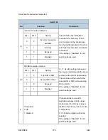
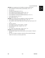
3. Pulse dial parameters (addresses 68054A to 68054F) are the values for 10 pps. If 20
pps is used, the machine automatically compensates.
4. The first ring may not be detected until 1 to 2.5 wavelengths after the time specified by
this parameter.
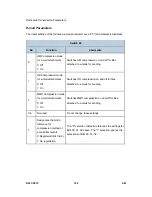
5. The calculated level must be between 0 and 10.
The attenuation levels calculated from RAM data are:
High frequency tone: – 0.5 x N680552/680554–3.5 dBm
– 0.5 x N680555 dBm
Low frequency tone:– 0.5 x (N680552/ N680553) –3.5 dBm
– 0.5 x (N N680553) dBm
N680552, for example, means the value stored in address 680552(H)
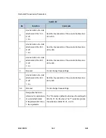
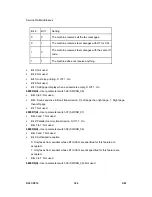
6. Ds and Di relay timing
68054A: Europe - Between Ds opening and Di opening, France - Between Ds closing
and Di opening
68054D: Europe - Between Ds closing and Di closing, France - Between Ds opening
and Di closing
7. Tone signals which frequency is lower than 1500Hz (e.g., 800Hz tone for AI short
protocol) refer to the setting at 6805B5h. Tones which frequency is higher than 1500Hz
refer to the setting at 6805B6h.
8. 68054A, 68054D, 68054E: The actual inter-digit pause (pulse dial mode) is the sum of
the period specified by the RAM addresses 68054A, 68054D, and 68054E.
Summary of Contents for D017
Page 1: ...D017 D018 D019 D020 D084 D085 SERVICE MANUAL 003320MIU...
Page 2: ......
Page 3: ...D017 D018 D019 D020 D084 D085 SERVICE MANUAL...
Page 4: ......
Page 5: ...D017 D018 D019 D020 D084 D085 SERVICE MANUAL 003320MIU...
Page 6: ......
Page 8: ......
Page 10: ......
Page 12: ......
Page 26: ......
Page 33: ...PRODUCT INFORMATION REVISION HISTORY Page Date Added Updated New None...
Page 34: ......
Page 46: ......
Page 51: ...Copier Installation D017 D018 D019 D020 D084 D085 2 5 SM Installation...
Page 175: ...PREVENTIVE MAINTENANCE REVISION HISTORY Page Date Added Updated New None...
Page 176: ......
Page 179: ...REPLACEMENT AND ADJUSTMENT REVISION HISTORY Page Date Added Updated New None...
Page 180: ......
Page 206: ...Photoconductor Unit PCU SM 4 26 D017 D018 D019 D020 D084 D085 6 Drum E White clip x1 F...
Page 262: ......
Page 264: ......
Page 293: ...TROUBLESHOOTING REVISION HISTORY Page Date Added Updated New None...
Page 294: ......
Page 299: ...Self Diagnostic Mode D017 D018 D019 D020 D084 D085 6 5 SM Trouble Shooting...
Page 303: ...Image Problems D017 D018 D019 D020 D084 D085 6 9 SM Trouble Shooting...
Page 309: ...Image Problems D017 D018 D019 D020 D084 D085 6 15 SM Trouble Shooting...
Page 323: ...ENERGY SAVING REVISION HISTORY Page Date Added Updated New None...
Page 324: ......
Page 333: ...D017 D018 D019 D020 D084 D085 SERVICE MANUAL APPENDICES...
Page 334: ......
Page 337: ......
Page 339: ......
Page 363: ......
Page 364: ...APPENDIX PM TABLES APPENDIX 2 PM TABLES REVISION HISTORY Page Date Added Updated New None...
Page 365: ......
Page 373: ......
Page 375: ......
Page 433: ......
Page 672: ......
Page 674: ......
Page 694: ......
Page 696: ......
Page 698: ......
Page 724: ......
Page 728: ......
Page 731: ...Covers SM 3 B793 Booklet Finisher B793 3 Remove the upper left cover C...
Page 745: ...Folder SM 17 B793 Booklet Finisher B793 6 Remove a connector 7 7 Remove 2 screws 8...
Page 746: ...Folder B793 18 SM 8 Remove the staple tray 9 9 Remove the guide 10 2 screws...
Page 790: ......
Page 792: ......
Page 794: ......
Page 816: ......
Page 818: ......
Page 822: ......
Page 826: ......
Page 1043: ...ARDF DF3030 D366 ARDF DF3030 REVISION HISTORY Page Date Added Updated New None...
Page 1044: ......
Page 1048: ......
Page 1074: ......
Page 1075: ...1 BIN TRAY BN3030 D367 1 BIN TRAY BN3030 REVISION HISTORY Page Date Added Updated New None...
Page 1076: ......
Page 1078: ......
Page 1084: ......
Page 1085: ...BRIDGE UNIT BU3020 D368 BRIDGE UNIT BU3030 REVISION HISTORY Page Date Added Updated New None...
Page 1086: ......
Page 1088: ......
Page 1097: ...DUPLEX UNIT AD3000 D369 DUPLEX UNIT AD3000 REVISION HISTORY Page Date Added Updated New None...
Page 1098: ......
Page 1100: ......
Page 1104: ......
Page 1112: ...Electrical Component D369 8 SM 4 Duplex transport motor B x 2...
Page 1121: ...BYPASS TRAY BY3000 D370 BYPASS TRAY D370 REVISION HISTORY Page Date Added Updated New None...
Page 1122: ......
Page 1124: ......
Page 1126: ......
Page 1128: ...Tray D370 2 SM 2 Remove the pins A x 1 each 3 By pass tray B x 1...
Page 1133: ...Feed SM 7 D370 Bypass Tray BY3000 D370 6 Separation pad D spring x 1...
Page 1138: ......
Page 1140: ......
Page 1142: ......
Page 1148: ......
Page 1150: ......
Page 1156: ......
Page 1176: ...Overview D372 20 SM No What Happens sure that the stapler is at its home position...
Page 1220: ......
Page 1222: ......
Page 1224: ......
Page 1254: ...Scanner Service Tables D383 6 SM Compression Notch Assignment...
Page 1260: ......
Page 1262: ......
Page 1264: ......

