background image

Installing Options

56

3

E

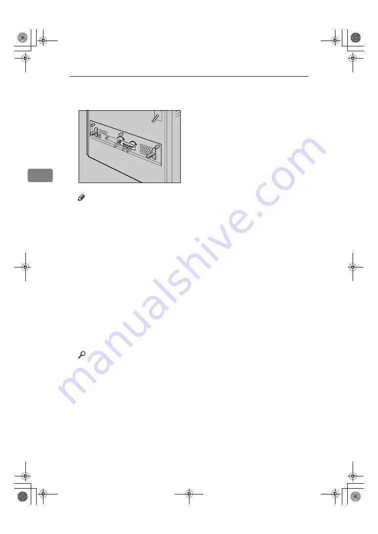
Tighten the two screws to secure
the 1284 interface board.

Note

Use the supplied adaptor to
make the connection with the
computer.

After finishing installation, you
can check the 1284 interface
board is properly installed:
Print the configuration page
from the “List/Test Print”
menu. If it is installed properly,
you will see “Parallel Interface”
for “Controller Option”.

If the 1284 interface board is not
installed properly, reinstall it
from step 

A

. If you cannot in-

stall it properly even after at-
tempting reinstallation, contact
your sales or service representa-
tive.

Reference

For printing the configuration
page, see p.30 “Test Printing”.

AET103S

GaiaP1GB_Setup-F4_FM_forPaper.book  Page 56  Friday, June 3, 2005  7:50 AM

Summary of Contents for Aficio CL4000DN

Page 1: ...The Netherlands RICOH EUROPE B V Groenelaan 3 1186 AA Amstelveen Phone 31 0 20 5474111 United Kingdom RICOH UK LTD Ricoh House 1 Plane Tree Crescent Feltham Middlesex TW13 7HG Phone 44 0 20 8261 4000...

Page 2: ...use The machine contains 7 mil liwatt 645 660 nanometer wavelength AlGaInp Laser Diode Safety precautions and interlock mech anisms have been designed to prevent any possible laser beam exposure to th...

Page 3: ...ilable Options 31 Option List 32 Option Installation Flow Chart 33 Installing Options 34 Caution when re installing the controller board 36 Attaching Paper Feed Unit Type 4000 37 Attaching Memory Unit...

Page 4: ...63 5 Configuration Ethernet Configuration 65 IEEE 802 11b Wireless LAN Configuration 68 IEEE 1394 Configuration 72 IP over 1394 72 SCSI print 73 6 Installing the Printer Driver Quick Install 75 Insta...

Page 5: ...operating system Microsoft Windows 98 operating system Microsoft Windows Millennium Edition Windows Me The product names of Windows 2000 are as follows Microsoft Windows 2000 Advanced Server Microsof...

Page 6: ...ock or fire Do not incinerate spilled toner or used toner Toner dust is flammable and might ignite when exposed to an open flame Disposal should take place at an authorized dealer or an appropriate co...

Page 7: ...omes into contact with toner or used toner wash the affected area thoroughly with soap and water If toner or used toner gets into your eyes flush immediately with large amounts of water Consult a doct...

Page 8: ...ting the paper feed unit carelessly or dropping it may cause an injury Do not touch the inside of the controller board compartment It may cause a machine malfunction or a burn When moving the machine...

Page 9: ...and handle the machine as indicated High temperature parts Turn off the main power and be careful when replacing fusing unit removing misfed paper The inside of this printer becomes very hot Do not to...

Page 10: ...r used toner Toner dust is flammable and might ignite when exposed to an open flame Disposal should take place at an authorized dealer or an appropriate collection site If you dispose of the used tone...

Page 11: ...delines for energy efficiency The ENERGY STAR Guidelines intend to establish an international energy saving system for developing and introducing energy efficient office equipment to deal with environ...

Page 12: ...ions all of which are described in the Safety Information section The statements above are notes for your safety If this instruction is not followed paper might be misfed originals might be damaged or...

Page 13: ...ull the levers marked A on either side of the machine To remove jammed paper press the button marked Z on the right side of the machine 3 Bypass Tray Up to 100 sheets of plain paper can be loaded Note...

Page 14: ...de down 7 Top Cover Open this cover when replacing the toner cartridge 8 Front Cover A Open Levers 9 Vent 10 Ventilator Releases heat from internal components to prevent overheating Malfunctions oc cu...

Page 15: ...er 4 Optional Interface Board Slots Insert an optional 1394 interface board 802 11b interface unit wireless interface board or 1284 interface board in this slot Up to two interface board can be insert...

Page 16: ...place Black PCU or Replace Color PCU appears on the display re place the photo conductor unit 4 Inner Cover Open this when replacing the photo con ductor units or intermediate transfer unit 5 Waste To...

Page 17: ...match the actually set size or type 5 Job Reset key When the printer is online press this key to cancel an ongoing print job 6 Online key Indicates whether the printer is online or offline Press this...

Page 18: ...o return to the previous condition on the display 11 U T keys Use these keys to increase or decrease values on the display when making set tings Keep the key pressed to quicken scroll ing and increase...

Page 19: ...e than nec essary These actions could cause an electric shock or fire Do not handle the plug with wet hands Doing so might cause an electrical shock Keep the machine in an area that is within optimum...

Page 20: ...are as follows A 50 cm 19 7 inches or more B 10 cm 4 inches or more C 10 cm 4 inches or more D 70 cm 27 6 inches or more Optimum Environmental Conditions Permissible and recommended temperature and h...

Page 21: ...smell To keep the workplace comfortable we recommend you keep it well ventilated Environments to Avoid Important Areas exposed to direct sunlight or strong light Dusty areas Areas with corrosive gase...

Page 22: ...defective items contact your sales representative Manuals and CD ROMs Setup Guide This manual Maintenance Guide CD ROM Printer Drivers and Utilities CD ROM Display Version Manuals HTML CD ROM Print V...

Page 23: ...r Calibration Sample Sheet Additional Documentation Note This package does not include an interface cable Please purchase one to use with your host computer See Appendix Maintenance Guide AET031S Gaia...

Page 24: ...ple by using the inset grips on both sides of the printer Important Leave the tape holding the pa per feed tray and cover in place while moving the printer Lower the machine slowly and carefully to pr...

Page 25: ...sfer unit Pinch it and then pull it out I Turn the green lever of the trans fer unit counterclockwise to un lock the unit J Remove the protective sheet as shown Pinch the orange tape and then pull it...

Page 26: ...r by grasping the handles on the left and right sides O Remove the clips protecting the mouths of all four toner cartridges P Close the top cover Q Put labels 1 on the front of the paper tray R Attach...

Page 27: ...an ap propriate collection site If you dispose of the used ton er cartridges yourself dis pose of them according to local regulations Do not store toner used toner or toner containers in a place with...

Page 28: ...holding the ton er cartridge E First install the yellow toner car tridge Holding the toner car tridge horizontally with the locking lever on the upper side install the toner cartridge bottom first and...

Page 29: ...re move toner cartridges Doing so results in toner leakage G Use the same procedures to insert the remaining three toner car tridges cyan C magenta M and black K H Close the top cover Important Do not...

Page 30: ...ops Then lift it slightly and then pull it out com pletely Place it on a flat surface B Pinch the green clips of the side guide and the end guide and ad just the guides to the paper size being loaded...

Page 31: ...close any gaps E Lift the front of the paper tray Tray 1 and slowly slide the pa per tray back until it stops Make sure the tray is fully inserted to prevent paper jams Reference For details about us...

Page 32: ...plug C Turn the power switch to a On The power indicator on the control panel lights up Note Wait until Ready appears on the display panel The machine may make a noise while initializing This noise d...

Page 33: ...lish A Press the Menu key The Menu appears on the dis play B Press the U or T key to dis play Language C Press the Enter key The following message appears on the display D Press the U or T key until t...

Page 34: ...pears C Press the U or T key to dis play the Config Page and then press the Enter key The following message appears and the configuration page is printed Note If printing is not normal check to see if...

Page 35: ...less Before installing options the machine should be turned off and unplugged for at least an hour Components inside the machine become very hot and can cause a burn if touched Before moving the mach...

Page 36: ...sic model printer HDD standard model printer Paper Feed Unit Type 4000 Hard Disk Drive Type 4000 Memory Unit Type D 128MB Memory Unit Type E 256MB IEEE 802 11b Interface Unit Type H IEEE 1284 Interfac...

Page 37: ...the hard disk drive Hard Disk Drive Type 4000 Install the hard disk drive to the controller board E Install the IEEE 1394 interface board IEEE 1284 interface board IEEE 802 11b interface unit or Blue...

Page 38: ...erior 1 Paper Feed Unit Type 4000 Loads up to 550 sheets of paper Up to two paper feed units can be in stalled on the printer Installed tray units are identified as Tray 2 and Tray 3 See p 37 Attachin...

Page 39: ...1284 Inter face Board Type A 3 NetworkDataProtectionUnitTypeB See p 57 Attaching Network Data Protection Unit Type B 4 Hard Disk Drive Type 4000 See p 45 Attaching Hard Disk Drive Type 4000 5 User Ac...

Page 40: ...efully follow the instruction be low to re install the controller board Re install the controller board into the machine by pushing the bottom center area of the board as shown in the illustration Imp...

Page 41: ...model code A Check the package contains the following Paper Feed Unit including a paper tray B Turn off the power and then un plug the power cable C Remove the orange fastening tapes from the paper fe...

Page 42: ...int the configuration page from the List Test Print menu If it is installed properly you will see Tray 2 or Tray 2 Tray 3 under the Options list If the paper feed unit is not in stalled properly reins...

Page 43: ...it you must make settings in the printer driver A Turn off the power and then un plug the power cable B Loosen the three screws securing the controller board The screws cannot be fully re moved C Gras...

Page 44: ...insert the module vertically G Press down the SDRAM module until it clicks into place H When replacing the default SDRAM module press down the levers on both sides to remove the default module Instal...

Page 45: ...installed Print the configuration page from the List Test Print menu If it is installed properly you will see the memory capacity for Total Memory The table below shows total SDRAM module capacities I...

Page 46: ...the package contains the following UserAccountEnhanceUnitTypeE B Turn off the power and then un plug the power cable C Loosen the three screws securing the controller board The screws cannot be fully...

Page 47: ...he controller board pressing it down until it clicks into place H Make sure that the user account enhance unit is firmly connected to the controller board I Fasten the four screws to attach the cover...

Page 48: ...counting Mod ule for Controller Option If the User Account Enhance Unit is not installed properly reinstall it from step A If you cannot install it properly even after attempting reinstallation contac...

Page 49: ...disk drive you must make the settings in the printer driver A Check the package contains the following Hard Disk Drive Flat Cable Power Cable Four Screws B Turn off the power and then un plug the powe...

Page 50: ...osen the four screws to remove the cover The screws cannot be fully re moved F You must install the hard disk drive unit as shown G Use the screws supplied with the hard disk drive to secure the unit...

Page 51: ...screws When the power is turned on the hard disk drive will be formatted automatically Note After finishing installation you can check whether the hard disk drive is properly installed Print the conf...

Page 52: ...nter key A check message appears Note If HD Format is not displayed on the display the hard disk drive is not installed properly Repeat the procedure from step A See p 45 Attaching Hard Disk Drive Typ...

Page 53: ...sing an account that has administrators access rights Before touching the 1394 interface board ground yourself by touch ing something metal to discharge any static electricity Static electric ity can...

Page 54: ...ter finishing installation you can check the 1394 interface board is properly installed Print the configuration page from the List Test Print menu If it is installed properly you will see IEEE1394 for...

Page 55: ...tents of the package for the following IEEE 802 11bInterface Unit Type H Interface Unit Card Antenna Antenna Cap B Turn off the power and then un plug the power cable C Loosen the two screws and re mo...

Page 56: ...ote After finishing installation you can check the 802 11b interface unit is properly installed Print the configuration page from the List Test Print menu If it is installed properly you will see IEEE...

Page 57: ...subject the Bluetooth inter face unit to physical shocks A Check the contents of the package for the following Bluetooth Interface Unit Type 3245 Interface Unit Card Antenna Cap B Turn off the power a...

Page 58: ...ation you can check the Bluetooth inter face unit is properly installed Print the configuration page from the List Test Print menu If it is installed properly you will see Bluetooth for Controller Opt...

Page 59: ...EEE 1284 Interface Board Type A B Turn off the power and then un plug the power cable C Loosen the two screws and re move the cover of the 1284 inter face board installation unit The removed cover is...

Page 60: ...ion page from the List Test Print menu If it is installed properly you will see Parallel Interface for Controller Option If the 1284 interface board is not installed properly reinstall it from step A...

Page 61: ...and then un plug the power cable C Remove the cover the controller board s central expansion card slot D Carefully insert the network data protection unit until the card clicks into the place E Reatta...

Page 62: ...Installing Options 58 3 GaiaP1GB_Setup F4_FM_forPaper book Page 58 Friday June 3 2005 7 50 AM...

Page 63: ...ould cause malfunctions Ethernet cable is not supplied with this machine Select your cable according to the network environment A Attach one ferrite core at the printer end of the Ethernet cable and t...

Page 64: ...the LED Lamps 1 Yellow lit when 100BASE TX is being used Unlit when 10BASE T is being used 2 Green lit when the printer is properly connected to the network AET123S GaiaP1GB_Setup F4_FM_forPaper book...

Page 65: ...s Server 2003 Mac OS 9 x and Mac OS X Windows 98SE Me supports USB1 1 speeds USB connection with Macintosh is only possible via the printer s USB port A Connect the square shaped connector of the USB2...

Page 66: ...ables create electromagnetic inter ference that could cause malfunctions A Turn off the printer and computer B Connect the cable to the interface socket of the IEEE 1284 interface board Important Volt...

Page 67: ...e board A Connect the interface cable to the 1394 interface board B Connect the other end to the host computer Note You can use either connector If you have an interface cable with a ferrite core conn...

Page 68: ...Connecting the Printer 64 4 GaiaP1GB_Setup F4_FM_forPaper book Page 64 Friday June 3 2005 7 50 AM...

Page 69: ...s setting only when it is necessary See Software Guide A Press the Menu key Menu appears on the display B Press the U or T key to dis play Host Interface menu and then press the Enter key The interfac...

Page 70: ...twork adminis trator J Press the U or T key to enter the left most entry field of the IP address and then press the En ter key Press the Enter key the screen changes and the next field can then be ent...

Page 71: ...select Auto the frame type detected by the printer is adopted If your network can use more than two frame types the print er may fail to select the correct frame type if Auto is selected In this case...

Page 72: ...ace unit cannot be used simultaneously with a standard ethernet interface In the SSID menu if blank is specified in 802 11b Ad hoc mode or Ad hoc mode ASSID ap pears A Press the Menu key Menu appears...

Page 73: ...el and then press the Enter key The channel currently used ap pears on the display H Press the U or T key to enter the channel and then press the Enter key I Set Trans Speed in the same way Note The f...

Page 74: ...twork activate the WEP set ting to be used for communica tion along with WEP Note Confirm the network adminis trator for the WEP Key to use WEP key can also be set using a Web browser For details see...

Page 75: ...s that can be entered is limited to 10 or 26 for hexadecimal and 5 or 13 for ASCII If you try to enter too many characters the following message appears hexadecimal ASCII For ASCII character strings e...

Page 76: ...ter key The IEEE 1394 setting menu ap pears D Press the U or T key to dis play IP over 1394 and then press the Enter key The IP over 1394 setting menu ap pears E Press the U or T key to select either...

Page 77: ...selected IP address is reset H Set other fields similarly and then press the Enter key The settings are made and after about two seconds the screen re turns to the IEEE 1394 setting menu I Set Subnet...

Page 78: ...en press the Enter key After the settings are made about two seconds later the screen re turns to the IEEE 1394 setting menu G Set Bidi SCSI print in the same way H Press the Online key Ready appears...

Page 79: ...ssion Log on as an Administrator The Quick Install is not available when using this printer under USB connec tion If you connect using USB see Software Guide A Quit all applications currently running...

Page 80: ...tion of the selected software click Cancel before installa tion is complete Restart the computer and then reinstall the other soft ware or printer drivers Auto Run may not work with certain operating...

Page 81: ...g system setting If this is the case launch Setup exe on the CD ROM root directory C Select an interface language and then click OK D Click Install manuals E Follow the instructions on the screen to c...

Page 82: ...uration 65 IEEE 1394 Configuration 72 IEEE 802 11b Wireless LAN Configuration 68 Configuration Page 30 Connecting the Printer IEEE 1394 Connection 63 Network Connection 59 Parallel Connection 62 USB C...

Page 83: ...Up 15 T Test Printing 30 Toner Cartridge 23 Tray 1 26 Turning the Power On 28 U Unpacking 20 USB Port 61 User Account Enhance Unit 32 42 W Where to Put the Printer 15 Wireless LAN 68 GaiaP1GB_Setup F4...

Page 84: ...80 MEMO GaiaP1GB_Setup F4_FM_forPaper book Page 80 Friday June 3 2005 7 50 AM...

Page 85: ...81 MEMO GaiaP1GB_Setup F4_FM_forPaper book Page 81 Friday June 3 2005 7 50 AM...

Page 86: ...82 GB GB G105 8600A MEMO GaiaP1GB_Setup F4_FM_forPaper book Page 82 Friday June 3 2005 7 50 AM...

Page 87: ...use The machine contains 7 mil liwatt 645 660 nanometer wavelength AlGaInp Laser Diode Safety precautions and interlock mech anisms have been designed to prevent any possible laser beam exposure to th...

Page 88: ...The Netherlands RICOH EUROPE B V Groenelaan 3 1186 AA Amstelveen Phone 31 0 20 5474111 United Kingdom RICOH UK LTD Ricoh House 1 Plane Tree Crescent Feltham Middlesex TW13 7HG Phone 44 0 20 8261 4000...

Reviews: