


2
WLS-C Wheel Loader Scale
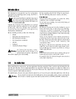
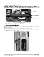
Figure 1-1. WLS-C Component List
1.1
Indicator Installation
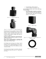
1. Use the bracket as a template to drill holes. Then, mount the bracket. Or, use the suction cup mount.
2. Fasten screws holding the bracket in place. The bracket can now accept the indicator.
3. Loosen the bracket handle shown in Figure 1-2, find the desired angle, and tighten the handle.
Figure 1-2. Bracket screwed in place
Wire
Connect To
PT1
Pressure transducer
PT2
Second pressure transducer (optional)
Prox1
Angle sensor on chassis
Prox2
Angle sensor on boom
Power (Brown/White)
Positive terminal on battery
Power (Green/Yellow)
Negative terminal on battery
Table 1-1. Cable Harness
Indicator
Indicator with wiring (see
Table 1-1 for cable details)
Pressure transducer
Pressure transducer cable
Angle sensor
Proximity
Sensor and Cable
Bracket handle


