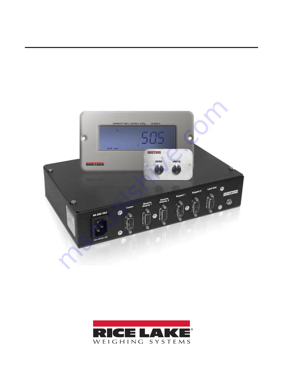
Tracer AV
Aviation Baggage Instrumentation
Installation Manual
PN 98316 Rev B
October
2
5, 2019
Page 1: ...Tracer AV Aviation Baggage Instrumentation Installation Manual PN 98316 Rev B October 25 2019...
Page 2: ...marks of their respective companies All information contained within this publication is to the best of our knowledge complete and accurate at the time of publication Rice Lake Weighing Systems reserv...
Page 3: ...ications 10 2 3 4 Digital I O 10 2 4 Board Removal 11 2 5 Replacement Parts 11 3 0 Configuration 12 3 1 Configuration Methods 12 3 1 1 EDP Command Configuration 12 3 1 2 Front Panel Configuration 12 3...
Page 4: ...5 2 2 Downloading Configuration Data from PC to Tracer AV 31 6 0 Appendix 32 6 1 Error Messages 32 6 1 1 Displayed Error Messages 32 6 1 2 Using the XE EDP Command 32 6 2 Status Messages 33 6 2 1 Usin...
Page 5: ...the warnings could result in injury or death Contact any Rice Lake Weighing Systems dealer for replacement manuals Failure to heed could result in serious injury or death Ensure the power cord is disc...
Page 6: ...remove the setup switch access screw on the Tracer AV See Figure 2 3 on page 5 Once the screw is removed use a small screwdriver or pen tip to press the setup switch The display changes to show the w...
Page 7: ...at standstill or within the specified motion band Some operations including tare function can only be done when the standstill symbol is shown lb and kg annunciators indicate the units associated wit...
Page 8: ...V to ensure all components are included and undamaged The shipping carton should contain the Tracer AV enclosure remote display remote keypad this manual two cables and a power cord If any parts were...
Page 9: ...for the power cord one to accommodate the load cell communications remote displays and keypads Figure 2 3 shows the assignments for the Tracer AV connections Details on pin assignments are shown in T...
Page 10: ...TVS1 TVS5 TVS4 3 3 R7 R4 C16 C4 DIGIN 1 J1 LOAD CELL U2 D1 U19 U6 U9 SERIAL 1 9 1 1 8 1 1 Gn d 20mA Gnd TxD Gnd Gn d DI 2 EXC E XC SEN SEN SIG 5 1 1 1 20mA RxD RxD TxD DI 1 SIG Micro processo r DISPLA...
Page 11: ...s Reserved 7 Figure 2 6 Panel Mount Housing Enclosure Dashed line represents RD 2 display location LCD Solid line represents RD 1 display location LED Figure 2 7 Remote Display Cutout for Panel Mount...
Page 12: ...Enclosure Dashed line represents RD 2 display location LCD for External Mounted Enclosure Solid line represents RD 1 display location Figure 2 9 Remote Display Cutout for External Mount 7 50 3 90 LCD...
Page 13: ...oad cell This DB 9 is connected to the CPU board on J1 see the table below for the pin assignments The DB 9 is for four wire installations so leave sense jumper JP1 and JP2 on The DB 9 is factory pinn...
Page 14: ...Digital outputs are typically used to control relays that drive other equipment In the Tracer AV the setpoint value will cause the display to flash Outputs are designed to sink not source switching c...
Page 15: ...on page 6 for connector locations 6 Remove the five screws from the CPU board then lift the board out of the enclosure To replace the CPU board reverse the above procedure 2 5 Replacement Parts Table...
Page 16: ...ront panel and provide some functions not otherwise available EDP commands can be used to simulate pressing front panel keys to configure the Tracer AV or to dump lists of parameter settings See Secti...
Page 17: ...the six digit display 2 Press Zero to accept the modified value 3 1 5 Editing Floating Point Decimal Point Position 1 By pressing Units navigate all the way to the right beyond all characters until th...
Page 18: ...Menu Figure 3 3 Default Calibration Menu DEFCAL Menu Parameter Choices Description SELECT 500 lb 300 lb 500 lb sets the scale to a primary of 500 lb x 1 lb and a secondary of 250 kg x 5 kg SP1 trip 50...
Page 19: ...y divisions Maximum legal value varies depending on local regulations Note For scales using linear calibration do not set the zero tracking band to a value greater than that spec ified for the first l...
Page 20: ...rom the immediate area of the scale Choices indicate the number of A D conversions that are averaged to obtain the displayed reading A higher number gives a more accurate display by minimizing the eff...
Page 21: ...nits See Level 3 submenu parameter descriptions DSPRAT 250MS 500MS 750MS 1SEC 1 5SEC 2SEC 2 5SEC 3SEC 4SEC 6SEC 8SEC Display rate Sets the update rate for displayed values Values are in milliseconds M...
Page 22: ...8 888 888 8888 88 Decimal point location Determines the location of the decimal point or dummy zeros in the secondary unit dis play DSPDIV 5D 1D 2D Display divisions Selects the value of minimum divis...
Page 23: ...has been set WVAL Display and edit the test weight value WSPAN Display and edit the span calibration A D count value REZERO Press Zero to remove an offset value from the zero and span calibrations Us...
Page 24: ...ERMIN CR LF CR Termination character Selects termination character for data sent from the EDP port EOLDLY 000 number End of line delay Sets the delay period in 0 1 second intervals from when a formatt...
Page 25: ...ss or net mode as long as the current weight is within the specified ZRANGE In OIML mode the scale must be in gross mode before it can be zeroed pressing the ZERO key in net mode clears the tare UID 1...
Page 26: ...and value used by the setpoint Level 3 submenus ENABLE OFF ON Turns setpoint ON or OFF KIND GROSS NET Specifies the setpoint kind and determines whether function is based on GROSS or NET weight GROSS...
Page 27: ...f the band value BNDVAL number The band value for either INBAND or OUTBND trip setpoints BNDVAL is ignored unless trip is set to INBAND or OUTBND HYSTER number Specifies a band around the setpoint val...
Page 28: ...n Figure 4 2 Default Calibration DEFCAL Menu 4 1 Default Calibration If using a 500 lb or 300 lb scale you can select it from the DEFCAL menu This automatically uses the settings shown in Table 4 1 fo...
Page 29: ...s to show the word DEFCAL 2 Remove all weight from the scale platform If test weights require hooks or other items place them on the scale for zero calibration 3 Press Units until the display reads CA...
Page 30: ...re About Calibration The following topics provide additional information about compensating for environmental factors Section 4 4 1 and diagnostic information for determining expected zero and span co...
Page 31: ...ax used for each of these groups 5 1 1 Key Press Commands Key press EDP commands Table 5 1 simulate pressing the keys on the 2 button keypad Most commands can be used in both setup and weighing mode S...
Page 32: ...yed in either setup mode or normal mode using the following syntax COMMAND ENTER Most parameter values can be changed in setup mode only Use the following command syntax when changing parameter values...
Page 33: ...8 888888 888880 PRI DSPDIV Primary units display divisions 1D 2D 5D PRI UNITS Primary units LB KG OZ TN T G NONE SEC DECPNT Secondary units decimal position 8 88888 88 8888 888 888 8888 88 88888 8 888...
Page 34: ...ALUE SP2 VALUE Setpoint value number SP1 TRIP SP2 TRIP Trip Higher Lower Inband Outbnd SP1 BNDVAL SP2 BNDVAL Band value number SP1 HYSTER SP2 HYSTER Hysteresis number SP1 ACCESS SP2 ACCESS Setpoint ac...
Page 35: ...r AVs with similar configurations are set up or when a Tracer AV is replaced To download configuration data connect the PC to the EDP port as described in Section 5 2 1 Place the Tracer AV in setup mo...
Page 36: ...ge Description Solution E A D A D physical error Contact Rice Lake Weighing Systems EEEROM EEPROM physical error EVIREE Virgin EEPROM Use TEST menu to perform DEFLT restore defaults procedure then rec...
Page 37: ...6 3 If more than one annunciator is lit the second number returned is the sum of the values representing the active annunciators Example If the annunciator status value returned on the ZZ command is 1...
Page 38: ...S Text or 100DMText Figure 6 1 Continuous Output Data Format Note STX POL wwwwwww UNIT G N S TERM ASCII 02 decimal Weight data 7 digits right justi ed with decimal point leading zero supression Overlo...
Page 39: ...Front Panel Display Characters Figure 6 2 shows the 7 segment LED character set used to display alphanumeric characters on the Tracer AV front panel Figure 6 2 Tracer AV Display Characters 9 E Q F R...
Page 40: ...cimal point is set to 8888 88 the indicator will overflow if 5 tons or more are applied to the scale With 5 tons applied and a conversion factor of 2000 the secondary unit s display needs five digits...
Page 41: ...iltering effect is 20 4 8 8 With this configuration each A D reading has a 1 in 20 effect on the displayed weight value Setting the filters to 1 effectively disables digital filtering 6 6 2 DFSENS and...
Page 42: ...le in Step 2 with a threshold weight value of 50 lb and a display division value of 5 lb 50 5 lb 10 DD DFTHRH should be set to 10 DD for this example 5 Finally set the DFSENS parameter high enough to...
Page 43: ...ero or negative no TARE ZERO yes CLEAR TARE positive no TARE yes CLEAR TARE Table 6 6 TARE and ZERO Key Functions for REGULAT Parameter Settings Serial Port Status LED1 EDP Port Flashing red TXD activ...
Page 44: ...inimum at 50 or 60 Hz Input Overload 12 V continuous static discharge protected RFI Protection Signal excitation and sense lines protected by capacitor bypass Analog Output Optional fully isolated vol...
Page 45: ......
Page 46: ...nada Mexico 800 321 6703 International 715 234 9171 Europe 31 0 26 472 1319 Rice Lake Weighing Systems is an ISO 9001 registered company Rice Lake Weighing Systems Specifications subject to change wit...