98316
Tracer AV
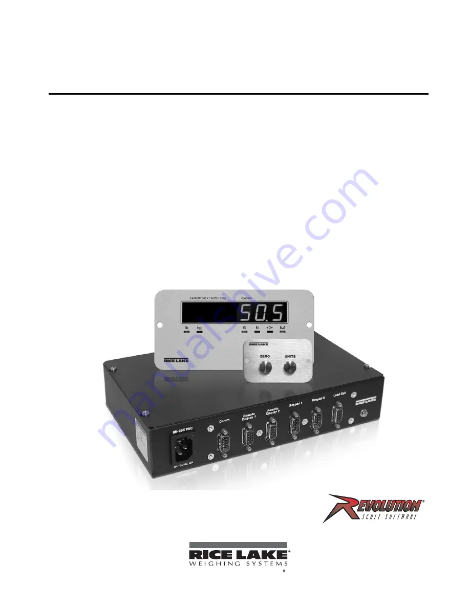
Aviation Baggage Instrumentation
Installation Manual
To be the best by every measure
Page 1: ...98316 Tracer AV Aviation Baggage Instrumentation Installation Manual To be the best by every measure...
Page 2: ......
Page 3: ...2 3 Cable Connections 4 2 3 1 Illustrations 5 2 3 2 Load Cells 7 2 3 3 Serial Communications 7 2 3 4 Digital I O 8 2 4 Board Removal 9 2 5 Replacement Parts 9 3 0 Configuration 10 3 1 Configuration M...
Page 4: ...ta to a Personal Computer 31 5 2 2 Downloading Configuration Data from PC to Tracer AV 31 6 0 Appendix 32 6 1 Error Messages 32 6 1 1 Displayed Error Messages 32 6 1 2 Using the XE EDP Command 33 6 2...
Page 5: ...ndary function for the setup mode The Tracer AV features include Four wire load cell connections remote sense connections are not provided The electronic data processing EDP port is full duplex RS 232...
Page 6: ...isplayed weight is a gross or net weight Center of zero Gross weight is within 0 25 graduations of zero This annunciator lights when the scale is zeroed Standstill Scale is at standstill or within the...
Page 7: ...Tracer AV to ensure all components are included and undamaged The shipping carton should contain the Tracer AV enclosure remote display remote keypad this manual two cables and a power cord If any par...
Page 8: ...the power cord one to accommodate the load cell communications remote displays and keypads Figure 2 3 shows the assignments for the Tracer AV connections Details on pin assignments are shown in Table...
Page 9: ...VS1 TVS5 TVS4 3 3 R7 R4 C16 C4 DIGIN 1 J1 LOAD CELL U2 D1 U19 U6 U9 SERIAL 1 9 1 1 8 1 1 Gn d 20mA Gnd TxD Gnd Gn d DI 2 EXC E XC SEN SEN SIG 5 1 1 1 20mA RxD RxD TxD DI 1 SIG Micro processo r DISPLA...
Page 10: ...6 Tracer AV Installation Manual Figure 2 6 Remote Display Cutout Figure 2 7 Remote Display Drawing...
Page 11: ...allations so leave sense jumper JP1 and JP2 on NOTE The DB 9 is factory pinned for four wire connections Leave sense jumpers JP1 and JP2 on 2 3 3 Serial Communications The pinned DB 9 connector marked...
Page 12: ...acer AV the setpoint value will cause the display to flash Outputs are designed to sink not source switching current Each output is a normally open connector circuit capable of sinking 250 mA when act...
Page 13: ...d cell cable J2 digital inputs J3 EDP J4 serial J6 digital outputs and J2 display See Figure 2 4 5 for connector locations 6 Remove the five screws from the CPU board then lift the board out of the en...
Page 14: ...ty allows configuration data to be retrieved from one Tracer AV edited then downloaded to another To use Revolution do the following 1 Install the Revolution module on a PC running Windows 98 or later...
Page 15: ...so display and edit zero calibration a d count value test weight value and span calibration a d count value CONFIG Configuration Configure grads zero tracking zero range motion band overload tare func...
Page 16: ...To save page space menu choices are shown in vertical columns The factory default setting appears at the top of each column in bold type Most menu diagrams are accompanied by a table that describes al...
Page 17: ...ions Maximum legal value varies depending on local regulations NOTE For scales using linear calibration do not set the zero tracking band to a value greater than that specified for the first lineariza...
Page 18: ...immediate area of the scale Choices indicate the number of A D conversions that are averaged to obtain the displayed reading A higher number gives a more accurate display by minimizing the effect of a...
Page 19: ...Level 3 submenu parameter descriptions DSPRAT 250MS 500MS 750MS 1SEC 1 5SEC 2SEC 2 5SEC 3SEC 4SEC 6SEC 8SEC Display rate Sets the update rate for displayed values Values are in milliseconds MS or sec...
Page 20: ...88 8888 88 Decimal point location Determines the location of the decimal point or dummy zeros in the secondary unit display DSPDIV 5D 1D 2D Display divisions Selects the value of minimum division size...
Page 21: ...t weight value WSPAN Display and edit the span calibration A D count value REZERO Press Zero to remove an offset value from the zero and span calibrations Use this parameter only after WZERO and WSPAN...
Page 22: ...from the EDP or printer port TERMIN CR LF CR Termination character Selects termination character for data sent from the EDP or printer port EOLDLY 000 number End of line delay Sets the delay period in...
Page 23: ...ht is at no load NONE allows tares to be cleared at any weight value NTEP and OIML modes allow a new tare to be acquired even if a tare is already present In CANADA mode the previous tare must be clea...
Page 24: ...display or print the date DATSEP SLASH DASH SEMI Specifies the date separator character TIMFMT 24HOUR 12HOUR Specifies the format used to display or print the time TIMSEP COLAN COMMA Specifies the tim...
Page 25: ...sed VALUE number Displays and edits the setpoint value TRIP HIGHER LOWER INBAND OUTBND Trips the setpoint when the weight is higher or lower than the setpoint value or is within or outside of the band...
Page 26: ...is used to check the software version and reg version installed in the Tracer AV You can also check the model Figure 3 11 Version Menu XXXXXXX ALGOUT XXXXXXX XXXXXXX VERS DIGIN SETPNT PROGRM PFORMT SE...
Page 27: ...ss screw on the Tracer AV See Figure 2 3 4 Once the screw is removed use a small screwdriver to press the setup switch The display changes to show the word DEFCAL 2 Remove all weight from the scale pl...
Page 28: ...progress When complete the A D count for the span calibration is displayed Press Zero again to store the span calibration value and go to the next prompt REZERO 7 The rezero function is used to remov...
Page 29: ...ings 4 5 More About Calibration The following topics provide additional information about compensating for environmental factors Section 4 5 1 and diagnostic information for determining expected zero...
Page 30: ...simulate pressing the keys on the 2 button keypad Most commands can be used in both setup and weighing mode Several of the commands serve as pseudo keys providing functions that are not represented by...
Page 31: ...se no spaces before or after the equal sign If you type an incorrect command or value the display reads Changes to the parameters are saved as they are entered but typically do not take effect until y...
Page 32: ...n REZERO Rezero LC CD Set deadload coefficient value LC CW Set span coefficient value Table 5 5 CALIBR EDP Commands Command Description Values EDP BAUD EDP port baud rate 300 600 1200 2400 4800 9600 1...
Page 33: ...nt kind GROSS NET SP1 VALUE SP2 VALUE Setpoint value number SP1 TRIP SP2 TRIP Trip Higher Lower Inband Outbnd SP1 BNDVAL SP2 BNDVAL Band value number SP1 HYSTER SP2 HYSTER Hysteresis number SP1 ACCESS...
Page 34: ...time hhmm enter using 24 hour format SX Start EDP streaming OK or EX Stop EDP streaming OK or RS Reset system XG Transmit gross weight in displayed units nnnnnn UU where nnnnnn is the weight value UU...
Page 35: ...eters to the PC as ASCII formatted text 5 2 2 Downloading Configuration Data from PC to Tracer AV Configuration data saved on a PC or floppy disk can be downloaded from the PC to a Tracer AV This proc...
Page 36: ...D converter requires recalibration Call RLWS Service EFCKSM Printer format checksum error Call RLWS Service ELCKSM Load cell calibration checksum error Recalibrate load cells EIDATA Internal RAM chec...
Page 37: ...mand can be used to remotely query which annunciators are currently displayed The ZZ command returns the currently displayed weight and a decimal number representing the LED annunciators currently lit...
Page 38: ...Text or 100DMText Figure 6 1 Continuous Output Data Format STX POL wwwwwww UNIT G N S TERM ASCII 02 decimal Weight data 7 digits right justi ed with decimal point leading zero supression Overload Unde...
Page 39: ...anel Display Characters Figure 6 2 shows the 7 segment LED character set used to display alphanumeric characters on the Tracer AV front panel Figure 6 2 Tracer AV Display Characters 9 E Q F R G S 0 H...
Page 40: ...pounds and the secondary decimal point is set to 8888 88 the indicator will overflow if 5 tons or more are applied to the scale With 5 tons applied and a conversion factor of 2000 the secondary unit...
Page 41: ...ltering effect is 20 4 8 8 With this configuration each A D reading has a 1 in 20 effect on the displayed weight value Setting the filters to 1 effectively disables digital filtering 6 6 2 DFSENS and...
Page 42: ...casional spikes to 75 lb record 50 lb as the threshold weight value 3 Place the Tracer AV in setup mode and set the digital filters DIGFLx to eliminate the vibration effects on the scale Leave DFTHRH...
Page 43: ...three seconds the test mode display automatically shifts to the first test menu function A DTST Figure 6 5 shows the Test Menu structure Table 6 5 summarizes the test menu functions Figure 6 5 Test Mo...
Page 44: ...emory Test Green Pass Red Fail LED ANA Red Not Implemented Analog Option Card Digital Input Output Status DO 1 Digital Out 1 On when lit active low DO 2 Digital Out 2 On when lit active low DI 1 Digit...
Page 45: ...Input Overload 12 V continuous static discharge protected RFI Protection Signal excitation and sense lines protected by capacitor bypass Analog Output Optional fully isolated voltage or current outpu...
Page 46: ...ot caused by accident misuse neglect alteration improper installation improper repair or improper testing RLWS shall be the sole judge of all alleged non conformities Such equipment has not been modif...
Page 47: ......
Page 48: ...PN 98316 02 11...