TM049 27L Continuous Flow Service Instructions
REV AL
– Issued April 2019
This document is stored and maintained electronically by Rheem Technical Support.
All printed copies are deemed “uncontrolled”.
78
EziSET
®
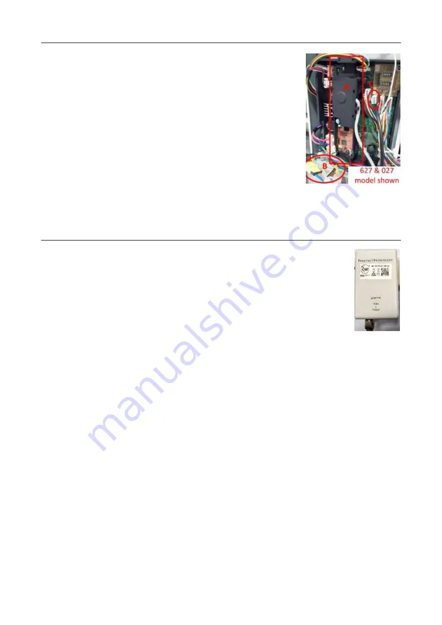
PCB: (Procedure 27)
1. Switch off the electrical supply at the power outlet to the water
heater.
2. Remove the front panel. Refer to Procedure 1.
3. Disconnect the EziSET
®
PCB black lead from terminal O of
the main PCB (refer C).
4. Disconnect the 2 x yellow wiring harnesses (refer B).
5. Disengage the top and bottom brackets that fix the EziSET
®
PCB (refer A) to the main PCB and remove.
6. Reassemble in reverse order of above.
Note:
The EziSET
®
PCB and PLT must be a matched paired
therefore the PLT plug is required to also be replaced if the EziSET
®
PCB requires
replacement (individual spare parts are not available, use complete EziSET
®
kit 052310
when replacing parts).
EziSET
®
Power Line Telecommunication (PLT): (Procedure 28)
1. Switch off the GPO that the PLT is plugged into.
2. Remove Ethernet cable from underside of PLT.
3. Remove PLT from GPO.
4. Reassemble in reverse order of above.
Note:
The PLT plug and EziSET
®
PCB must be a matched paired therefore
the EziSET
®
PCB is required to also be replaced if the PLT plug requires
replacement (individual spare parts are not available, use complete EziSET
®
kit 052310
when replacing parts).


