


INSTALLATION
Only standard mechanics tools, torque wrenches, inside
micrometer, dial indicator, straight edge, spacer bar, and feeler
gauges are required to install gear couplings. Lock out starting
switch of prime mover. Clean all parts using a non-flammable
solvent. Check hubs, shafts, and keyways for burrs. DO NOT
heat clearance fit hubs. Use a lubricant that meets the
specifications on Page 2. Pack sleeve teeth with grease and
lightly coat seals with grease BEFORE assembly. The required
amount of grease is listed in Table 4. Make certain flange
fasteners are tightened to the required torque listed in Table 4.
Interference Fit Hubs —
Unless otherwise specified, gear
couplings are furnished for an interference fit without setscrews.
Heat hubs to 275°F(135°C) using an oven, torch, induction
heater, or an oil bath.
CAUTION:
To prevent seal damage DO NOT heat hubs beyond
a maximum temperature of 400°F (205°C.)
When an oxy-acetylene or blow torch is used, use an excess
acetylene mixture. Mark hubs near the center of their length in
several places on hub body with a temperature sensitive crayon,
275°F (135°C) melt temperature. Direct flame towards hub bore
using constant motion to avoid overheating an area.
WARNING:
If an oil bath is used, the oil must have a flash point
of 350°F (177°C) or higher. Do not rest hubs on the bottom of
the container. Do not use an open flame in a combustible
atmosphere or near combustible materials
.
Maximize Performance & Life
The performance and life of couplings depend largely upon how
you install and maintain them. Before installing couplings, make
certain that foundations of equipment to be connected meet
manufacturers’ requirements. Check for soft foot. The use of
stainless steel shims is recommended. Measuring misalignment
and positioning equipment within alignment tolerances is
simplified with an alignment computer. These calculations can
also be done graphically or mathematically, and allow the
incorporation of “cold offsets”, which will compensate for shaft
position changes due to thermal growth.
Balanced Couplings
The fasteners provided are matched sets and must not be mixed
or substituted. Assembly balanced couplings are match marked
and must be assembled with mating match marks aligned. In
some sizes, the flanges are not match
marked. Coupling flanges must be
assembled with O.D.’s aligned to
within .002". Component parts of
assembly balanced couplings must
not be replaced without re-balancing
the complete assembly.
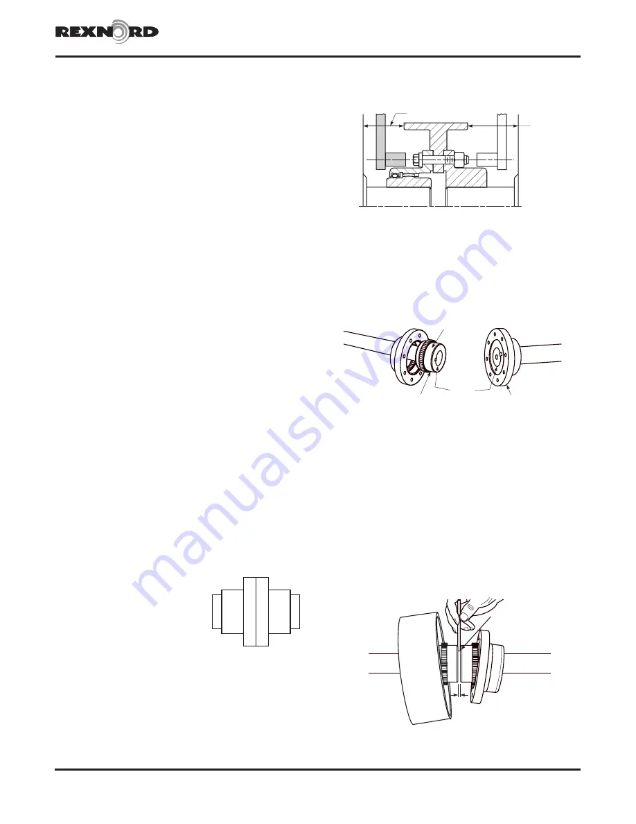
1 — Check Wrench Clearance
Check wrench clearance as shown above. If inadequate, refer
to Falk for an engineering review.
2 — Mount Flanged Sleeves, Seals, Hubs &
Brakewheel
Place the flanged sleeves WITH seal rings on shafts BEFORE
mounting flex hubs. Mount flex or rigid hubs on their respective
shafts, as shown above, so that each face is flush with the end
of its shaft. Place the brakewheel on the flex hub shaft (for Type
G62, on the shaft that allows the most hub exposure for
coupling alignment). NOTE: Brakewheel bolt flange may not be
on center line of wheel. In these cases, misalignment between
wheel and brake will occur if wheel is placed on shaft
incorrectly. Allow hubs to cool before proceeding. Seal keyways
to prevent leakage. Insert setscrews (if required) and tighten.
Position equipment in approximate alignment with approximate
hub gap specified in Table 4.
3 — Gap & Angular Alignment
Rexnord Industries, LLC, Coupling Group
458-610
5555 S. Moorland Rd., New Berlin, WI 53151-7953 USA Telephone : 262-796-4060
September 1999 (PDF Revision)
Fax: 262-796-4064 e-mail: [email protected] web: www.rexnord.com
Supersedes 6-82
Falk™ Double & Single Engagement Gear Couplings
•
Install. & Maint.
Type G62 & G66
•
Sizes 1010 thru 1070G
(Page 3 of 6)
A1
A1
A1
A1
B1
B1
CLEARANCE
ALLOW
CLEARANCE
WHEN BOLT
IS INSERTED
FROM THIS
SIDE
NOTE: Longer
shank toward
gap end.
NOTE:
Flush here.
FLEX HUB
RIGID HUB
ALWAYS MEASURE
TO SAME DEPTH
GAP
Type G62


