background image


The ZM 300 Ultra Centrifugal Mill 


24 


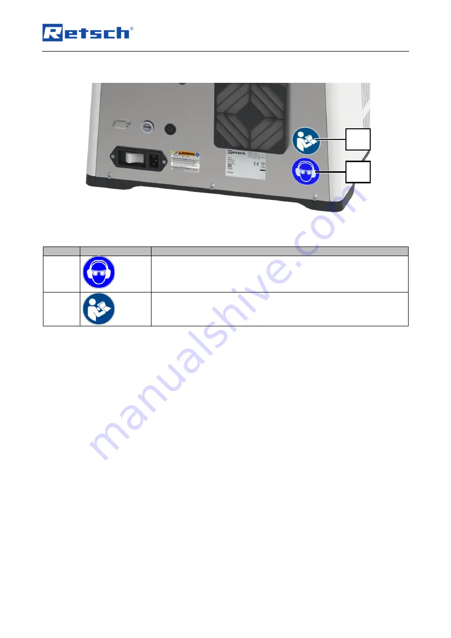
3.3  Instructions on the device  


Fig. 6:

 Notice on the device 


Position 

Element  

Meaning 


Eye and hearing protection must be worn when operating the device without noise 
protection funnel. This PPE prevents eye injuries if sample material is ejected 
during grinding and exposure to noise that can be caused by the grinding noise of 
the device. 


This instruction sign is located on the rear of the device near the main switch and 
indicates the need to read the operating instructions before using the device. 

Summary of Contents for ZM 300

Page 1: ...Retsch GmbH 42781 Haan Retsch Allee 1 5 Germany 04 04 2022 Version 0001 Manual Ultra Centrifugal Mill ZM 300 Translation...

Page 2: ...2 Copyright Copyright by Retsch GmbH Retsch Allee 1 5 42781 Haan Germany...

Page 3: ...nical data 18 3 2 Views of the device 19 3 2 1 Front 19 3 2 2 Back 21 3 2 3 View of grinding tools and tools und cassette 22 3 2 4 View of the device with additional equipment 23 3 3 Instructions on t...

Page 4: ...nt 66 7 7 6 Operating Hours 66 7 7 7 Software Update 67 8 Error messages and remarks 68 8 1 Error messages 68 8 2 Remarks 70 9 Installing additional equipment 71 9 1 Paper filter with support 71 9 1 1...

Page 5: ...Notes on the manual 5...

Page 6: ...ve of Machinery 2006 42 EC 1 1 Disclaimer Die vorliegende Bedi enungsanleitung w urde mi t gr ter Sorgfalt erstellt Technische nderungen si nd vor behalten F r Personensch den die aus der Nichtbefolgu...

Page 7: ...of the touchscreen display are labelled with a T in the Controlling the device using the touchscreen display chapter for better orientation The Retsch ZM 300 Ultra Centrifugal Mill is usually describe...

Page 8: ...s Source of danger Possible consequences if the danger is ignored Instructions and information on how to avoid the risk Average to slight injuries may result if the Caution sign is disregarded There i...

Page 9: ...ntended with this device and with knowledge of the technical documentation available here operational safety is assured 2 1 Use of the Device for the Intended Purpose The Retsch ZM 300 Ultra Centrifug...

Page 10: ...nt safety regulations 2 3 2 Personnel Ensure that only skilled personnel are deployed who due to their training and experience are qualified to recognise risks and avoid potential hazards Personnel sh...

Page 11: ...e been instructed in the safe handling of the device Work on the electrical equipment on the device Qualified electricians who on the basis of their technical training knowledge and experience are abl...

Page 12: ...Your supplier or Retsch GmbH directly Service address 2 5 Safety equipment Hood lock The device is equipped with an automatic hood lock The device hood is automatically locked by the locking pin when...

Page 13: ...the main switch or by disconnecting the device from the power supply 2 6 Emergencies The device can be switched off at any time by the main switch at the back of the device After the device has been s...

Page 14: ...protection funnel Before operating the device take measures to allow for limited communication while the device is in operation Emergency release of the device hood may only be carried out when the g...

Page 15: ...not feed any sample material before the grinding gear is running Mechanical components can be damaged when starting with sample material in the cassette Do not feed sample material too quickly and do...

Page 16: ...has received adequate instruction on operating and maintaining the device The operator has received the Manual taken note of it and as a consequence has all information needed for safe operation and...

Page 17: ...determined by the following factors Rotor type Rotor speed Sieve Characteristics fracture behaviour of the materials fed in as sample material Thanks to the effective grinding process and the wide ran...

Page 18: ...tte is 300 ml 600 ml with the large volume cassette This information only applies if there is no increase in volume of the sample during grinding Maximum fill quantity The maximum fill quantity of the...

Page 19: ...he grinding gear 1 1 Hopper for noise reduction When feeding sample material of 4 mm this hopper can be inserted into the feed hopper This funnel reduces the discharge of fine sample material as well...

Page 20: ...ioning the through cassette 10 Interior This is where the grinding tools and the cassette are located 11 Rotor shaft Support for grinding tools and cassette 12 Rubber seal Seals the passage of the loc...

Page 21: ...17 DR 100 interface For connection to the DR 100 feed unit 18 USB port For connection of a USB medium to update the control software 19 RPIO interface For the connection of the Retschbox 20 Rubber co...

Page 22: ...tools and cassette No Component Function 23 Cassette lid Closes the cassette 24 Ring sieve Selects the sample material 25 Rotor Grinds the sample material 26 Cassette For collection of the sample mat...

Page 23: ...rator 32 Hopper of the DR 100 feed unit For feed of sample material with the DR 100 feed unit 33 DR 100 feed unit For automatic feeding of higher quantities of sample material mostly in combination wi...

Page 24: ...ating the device without noise protection funnel This PPE prevents eye injuries if sample material is ejected during grinding and exposure to noise that can be caused by the grinding noise of the devi...

Page 25: ...cle number 4 Serial number 5 Manufacturer address 6 CE marking 7 Disposal sign 8 Barcode 9 Voltage variant 10 Supply frequency 11 Power 12 Current rating 13 Number of fuses 14 Fuse design and rating I...

Page 26: ...e knocked shaken or thrown during transport Move the device gently during transport NOTICE N4 0014 Complaints Incomplete delivery or transport damage The forwarding agent and Retsch GmbH must be notif...

Page 27: ...range 5 C to 40 C ambient temperature of the device Installation height max 2 000 m above sea level Ambient temperature 5 C 40 C Maximum relative humidity 80 at ambient temperatures 31 C For ambient t...

Page 28: ...serve the values on the type plate Electronic and mechanical components may be damaged Connect the device only to a mains supply matching the values on the type plate WARNING When connecting the power...

Page 29: ...device match 2 Plug the mains lead into the power connection 15 on the back of the device 3 Connect the mains plug to the electrical connection socket 4 Switch on the device with the main switch 16 a...

Page 30: ...ation without safety equipment If the device is operated without safety equipment splash back protection or fill hopper items of clothing or parts of the body can get into the grinding chamber The rot...

Page 31: ...the rear of the device Fig 10 The touch display 6 is activated and the background of the control dial 7 briefly lights up in blue The device is ready for use No Component 6 Touch display 7 Control dia...

Page 32: ...od Open the interior as follows Fig 12 Device with closed device hood 1 Switch on the device The touch display 6 of the device is activated and the background of the control dial 7 briefly lights up i...

Page 33: ...d 2 by hand and hold it in closed position The device emits an acoustic signal Fig 15 Device with closed device hood The device hood 2 is automatically locked by the locking pin 8 and the interior 10...

Page 34: ...ating the emergency release Wait until all parts of the device have stopped moving Situations such as a power failure may require emergency release of the device hood to access the interior of the dev...

Page 35: ...the interior 10 7 Remove the key 4 1 from the opening 4 8 Solve the situation that made the emergency release necessary 9 Connect the device to the power supply 10 Switch on the device The touch displ...

Page 36: ...ace Before grinding of sample material the required grinding tools and the cassette must be inserted into the interior of the device No special tools are required to insert the grinding tools into the...

Page 37: ...device is correctly engaged Fig 21 Ring sieve and rotor 8 Place the rotor 25 around the rotor shaft 11 over the labyrinth disc 27 9 Ensure that the driver is correctly engaged on the rotor shaft 11 1...

Page 38: ...se the device hood 2 and hold it in closed position for approx 2 seconds Fig 23 Device with closed hood The device hood 2 is automatically locked by the locking pin 8 Fig 23 No Component 2 Device hood...

Page 39: ...e sample material CAUTION C6 0004 Risk of injury Explosive or flammable samples Samples can explode or catch fire during the grinding process Do not use any samples in this device that carry a risk of...

Page 40: ...ents used before grinding any other sample material Observe the safety data sheets of the sample materials NOTICE N10 0003 Damage to mechanical components Rotor blockage When feeding coarse solid samp...

Page 41: ...33 Fig 24 Fig 25 Device with additional equipment With the DR 100 feed unit 33 larger quantities of sample material can be fed automatically When feeding large quantities of sample material operation...

Page 42: ...et the parameters for grinding on the touch display 6 and with the control dial 7 2 Press on the touch display 6 to start the grinding process 3 Slowly feed the sample material into the noise protecti...

Page 43: ...op are activated On the display 35 of the DR 100 feed unit 33 pc is displayed Fig 28 Device with DR 100 feed unit 5 Loosen the toggle screw 38 of the base plate and swivel away the DR 100 feed unit 33...

Page 44: ...y 7 Control dial 10 Interior 28 Chute of the DR 100 feed unit 29 Cyclone separator 30 Collection receptacle of cyclone separator 32 Hopper of the DR 100 feed unit 33 DR 100 feed unit 34 Toggle screw f...

Page 45: ...es Fluorspar feldspar Rotor with wear resistant coating Adjust the ring sieve with wear resistant coating to the desired final fineness level This type of rotor should be used if any abrasion of the s...

Page 46: ...caused by liquid nitrogen Use of liquid nitrogen during cryogenic grinding Liquid nitrogen has a boiling point of 196 C and causes burn like injuries and frostbite if there is skin and eye contact Ta...

Page 47: ...ances The resulting overpressure when the nitrogen is heated could blow the mill open Embrittlement with liquid nitrogen is often not necessary Sample material that is difficult or impossible to grind...

Page 48: ...on T1 Status display Automatic hood opening on off Signalling device on off T2 Navigation area Selection of the operating modes Manual and Program as well as access to the System settings menu T3 Para...

Page 49: ...Controlling the device using the touchscreen display 49 Fig 31 Display after switching on the ZM 300 Fig 32 Display after closing the lid T4 2 T4 1 T3 2 T3 1 T2 1 T2 2 T1...

Page 50: ...s function can only be selected when the DR 100 feed unit is connected and switched on The conveying speed set manually on the feed unit is overwritten by the value set on the device when the grinding...

Page 51: ...main menu the parameters for the grinding process can be configured and grinding be started Opens the device hood After switching on the device the touch display shows a prompt to open and close the...

Page 52: ...nnected and switched on Automatic stop Automatic stop of the device after mm ss The device detects when there is no more sample material and stops automatically after the specified time This function...

Page 53: ...e end of grinding Remote Pairing the device with a mobile terminal device myRetsch Displays QR code on the display for access to the web portal 7 3 Operating modes and navigation The following operati...

Page 54: ...ed start in mm ss minutes seconds When operating with DR 100 connected Feed rate of the DR 100 feed unit in 0 to max speed in When operating with DR 100 connected Automatic stop in mm ss minutes secon...

Page 55: ...preset minutes seconds mm ss value The display counts down to zero in steps of one second DR 100 conveying speed With the DR 100 feed unit connected the control dial can be used to set the conveying...

Page 56: ...ows the load on the drive When grinding observe the performance indicator on the touch display to prevent the sample material from being fed in too quickly Fig 35 Performance indicator Power peaks are...

Page 57: ...ters can be stored in the program preset and called as Standard Operating Procedures SOP when required Eight program presets are available The following parameters can be stored in individual programs...

Page 58: ...tch to program mode The display switches to the current program The program number is displayed next to the symbol Swipe from right to left or from left to right on the touch display in the Parameter...

Page 59: ...ion Function T2 3 Manual mode Manual mode or return to manual mode T3 5 Program sections Displays the current parameters of the programs T4 3 Scroll bar Indicator for the position of the program overv...

Page 60: ...ves the program Press the button to edit the program Enter the desired parameters The process can be cancelled by pressing All settings are discarded 7 6 3 Save a Programme Press the button to save th...

Page 61: ...Function T5 MyRetsch Displays a QR code in the display T6 Signalling device on off This can be used to switch the signal device on or off T7 Remote connection When this function is selected the devic...

Page 62: ...e device using the touchscreen display 62 Fig 40 Overview 2 System settings Element Description Function T9 Display brightness Setting of the display brightness T10 Date and time Setting of the date a...

Page 63: ...ion Display of the installed firmware version T12 Serial number The serial number of the device is displayed here T13 Service environment Enables access to the service environment for service technici...

Page 64: ...code This can be read in with a smartphone with the appropriate software and internet connection Afterwards the website of the device can be accessed directly which provides additional information su...

Page 65: ...ay are inactive Fig 43 Inactive touch display after remote connection For further information on connecting the device to the WLAN module and controlling the device remotely please refer to the separa...

Page 66: ...ected by pressing the section T13 the USB interface is activated and On is displayed below the symbol However no other functions are carried out Deactivate the service environment by pressing the sect...

Page 67: ...be formatted in the FAT32 file system USB 3 0 mediums are not supported The main directory may only contain the software to be installed The software is then automatically detected by the device Pres...

Page 68: ...process can be carried out with reduced speed Switch off the main switch and wait 30 seconds before switching the device on again E12 Motor brake Too many braking steps detected causing excessive heat...

Page 69: ...nd actual speed of the drive deviate from each other Switch off the main switch and wait 30 seconds before switching the device on again If necessary remove any foreign bodies from the interior of the...

Page 70: ...the process Remarks offer the user additional information but do not represent any device or program faults MM 500 cryo Reference code Description Measures H10 Motor is overheated The drive can withst...

Page 71: ...itional equipment 9 1 Paper filter with support The device can be fitted with a paper filter as collecting receptacle With the paper filter it is possible to collect a large quantity of sample materia...

Page 72: ...rt 31 1 12 Fit the filter support 31 1 with the through cassette 26 1 and connect them with the rubber seal 31 4 The paper filter bag is installed and the device is ready for use Fig 46 No Component 2...

Page 73: ...and grinding tools 1 Switch on the device 2 Open the device hood 2 3 Switch off the device while the device hood 2 is open The device is switched off and the device hood 2 is open Fig 47 4 If inserted...

Page 74: ...collection receptacle 30 are aligned 16 Tighten the screws on the support after height adjustment 17 Attach the collection receptacle 30 to the cyclone separator 29 Fig 49 Fig 50 The cyclone separator...

Page 75: ...ates of the device and the DR 100 feed unit The best choice is a multiple socket to which the device and the DR 100 feed unit are connected but no other devices 9 3 1 Installing the DR 100 feed unit F...

Page 76: ...DR 100 8 Align the vibrating chute 28 over the noise protection funnel 1 1 9 Lower the hopper 32 onto the chute 28 fill in the sample material Afterwards lift the hopper 32 off the chute 28 to operati...

Page 77: ...d ready for use No Component 1 1 Hopper for noise reduction 5 Stand opening 6 Touch display 7 Control dial 16 Main switch 17 Interface for DR 100 feed unit 28 Chute of the DR 100 feed unit 32 Hopper o...

Page 78: ...water Cleaning the device with water can lead to life threatening injuries caused by an electric shock if the device has not been disconnected from the power supply Only carry out cleaning work on the...

Page 79: ...1 1 with a vacuum cleaner or brush 6 If necessary hold the feed hopper 1 impact protection 0 and funnel for noise protection 1 1 under running water 7 Allow the feed hopper 1 impact protection 0 and f...

Page 80: ...with the main switch 16 on the back while the device hood 2 is open Touch display 6 goes out The device is switched off and the device hood 2 is open Fig 57 Fig 58 Interior 5 If inserted remove the g...

Page 81: ...he device The touch display 6 is activated and the background of the control dial 7 briefly lights up in blue 13 Close the device hood 2 by hand and hold it in closed position for approx 2 sec The dev...

Page 82: ...th disc 27 from the interior 10 2 Clean the grinding tools 24 25 27 and cassette 26 with lid 23 depending on the degree of soiling individually with a brush a vacuum cleaner a damp cloth and or a suit...

Page 83: ...e the filter frame 22 on the back of the device by releasing it with a screwdriver Fig 62 Position of filter covers 3 Clean the filter frame filter protection grid and filter mat 22 22 1 22 2 with a v...

Page 84: ...f the device with the main switch 16 on the back while the device hood 2 is open Touch display 6 goes out The device is switched off and the device hood 2 is open Fig 63 Fig 64 Locking pin 5 Check the...

Page 85: ...itch 16 at the rear of the device Touch display 6 goes out Device is switched off 2 Remove the filter frame 22 as previously described 3 Replace the heavily soiled filter mat 22 2 and clean the filter...

Page 86: ...completed correctly and in full 1 Download the returned goods consignment note from the download section Miscellaneous on the Retsch GmbH website http www retsch de de downloads sonstiges 2 In the ev...

Page 87: ...n for the device and on the myRetsch site see Controlling the device using the touchscreen display myRetsch Information about wearing parts and small accessories can be found in the complete catalogue...

Page 88: ...the business to business area to which this product is classified may no longer be disposed of with municipal or household waste To document this the devices are provided with the disposal label Fig...

Page 89: ...e separator 41 44 74 Cyclone separator with collecting receptacle 73 D Date and time 62 Declaration of no objection 86 Delete 60 Device control area 48 Device designation 25 Device hood 19 32 33 35 38...

Page 90: ...possible final fineness level 18 Maximum relative humidity 27 MyRetsch 61 64 N Nameplate 21 Navigation area 48 Noise emissions 18 Noise protection funnel 12 13 41 42 Notes on the manual 6 Number of fu...

Page 91: ...rs 12 Supply frequency 25 Support 23 Switching the device off 31 Switching the device on 31 Symbols 7 system settings 61 System settings 50 61 T Target group 9 Technical data 18 Temperature fluctuatio...

Page 92: ......

Page 93: ...Copyright Copyright by Retsch GmbH Retsch Allee 1 5 42781 Haan Germany...

Reviews: