Page 11 of 91
© Retrotec 2017
be heated in hot water before being handled. Be careful to dry all water from the tubing prior to connecting since
water in the tube is a major source of measurement error.
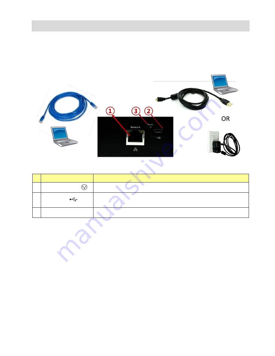
Connections on the bottom of the gauge provide a USB charging input and remote control port as well as
an Ethernet remote control port. An Ethernet cable of type Cat5e or Cat6
from the “Network” po
rt can
connect the gauge directly to a PC, to an Ethernet switch, or to a router. Ethernet cables have a maximum
length of 328 ft (100 m); over longer lengths signal strength may be compromised.
Figure 3: Connect charger or remote computer control
Table 2: Physical connections from gauge to a computer or charger are on the bottom of gauge
gauge port
connection
1
“Network” cable port
A Cat5e or Cat6 Ethernet cable can connect the gauge to a computer, a switch, or a router,
in order to control fan and/or read the gauge measurements via the computer
2
USB cable port
Connect the
USB “A”/“Micro
-
B” cable to a PC or the supplied AC power
adapter in order to
charge the internal battery of the gauge.
Connect the USB to a computer to update the software internal to the gauge (firmware).
3
“Reset”
Press a paper clip into the hole to reset the gauge
–
forces the gauge to turn off and back
on again.
2.2
Charge the battery in the gauge
The gauge is charged at the factory, but you can plug it in to ensure a full charge before each test. Connect
the USB cable to the AC power adapter to charge the gauge battery. Charging using the AC power adapter
is the only way to fully charge the gauge. Plugging the gauge into a computer USB port will extend the
length of the charge but the gauge will eventually need to be recharged using the AC power adapter.
With the AC adapter, a full charge will be completed in about four hours. A fully charged gauge will last for
approximately 8 hours without a recharge. For details see 2.5.5


