background image


Revision 1.2D 


Page 5 of 17 


www.resourcedm.com 

ML Switch User Guide


Warning 


Please Note 

The specifications of the product detailed on this 
Set-Up  Guide  may change without notice. RDM 
Ltd. shall not be liable for errors or for incidental 
or consequential damages, directly and indirectly, 
in connection with the furnishing, performance or 
misuse of this product or document.


Ensure that all power is 
switched off before   
installing or maintaining 
this product 

RS232 Lead Lengths 

 
RS232 patch lead maximum length must not exceed 15 metres. (Ports 1 - 10) 
 
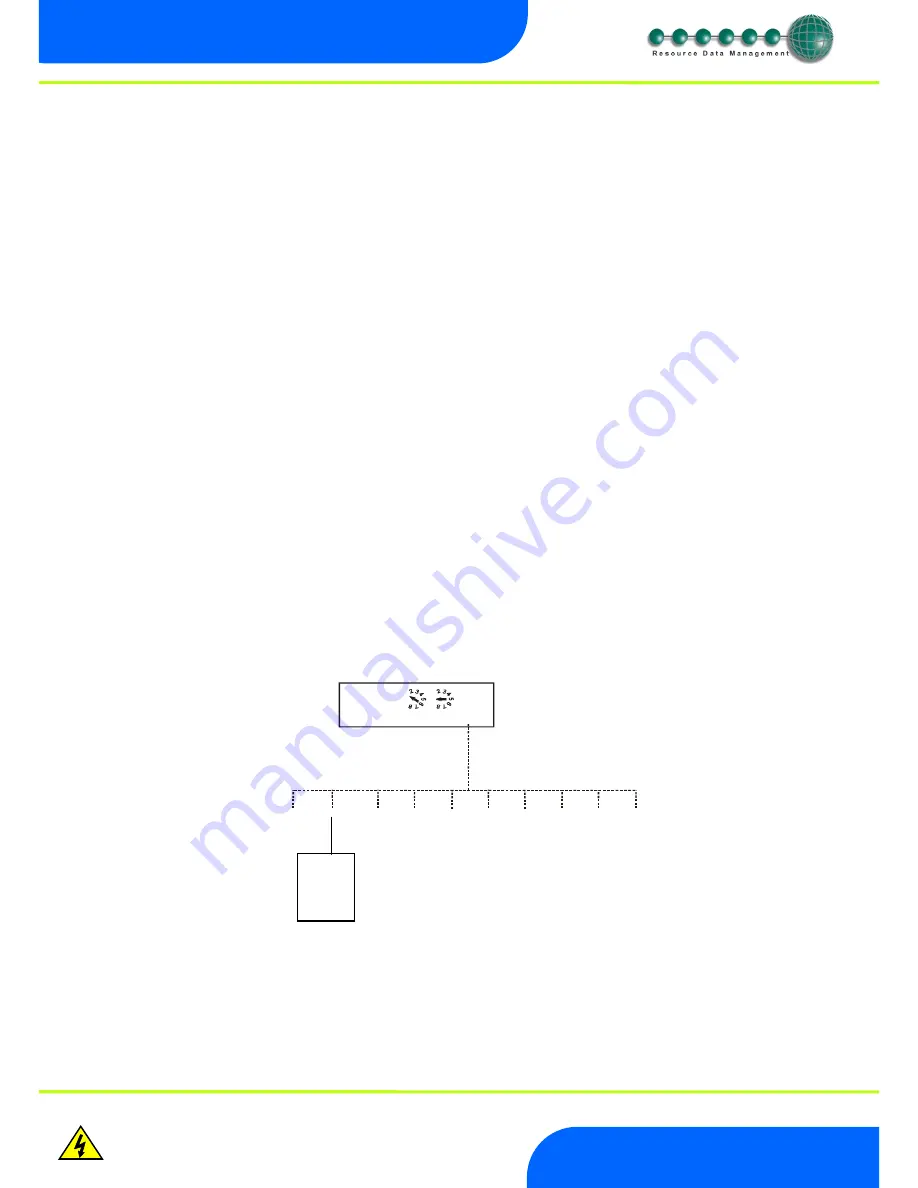
The 3-character address that will be seen on the system front end is determined by the position of the two Network ID rotary switches 
and the port the controller has been connected to, unless the connected controller has its own network ID rotary switches, in which case 
the controller ID will override the switch settings. 


Connection to other IP equipment 

 
Use a standard CAT5 patch lead to connect other IP equipment to the ML Switch (such as a Futura IP module) into the 10/100 Base T 
ports 1, 2 or 3. 


Connection to another ML Hub/Switch or Other Ethernet Hub/switch 


Use a standard CAT5 patch lead from any of the three 10/100 Base T ports into any of the three 10/100 Base T ports on the upstream 
ML Switch. The three 10/100 Base T ports are all self configuring. 


Connection to a Data Manager/Director 

 
Use a standard CAT5 patch lead and connect the Data Manager or Data Director to one of the three 10 Base T ports. 


10/100 Base T connectors 

 
The three 10/100 Base T connectors have 2 LED’s adjacent to them: The green LED; when static, indicates that the connection to the 
device is good, the green LED then flickers when data is being transmitted. 
When the amber LED is permanently on it indicates that the connection is full duplex and if there is an error or fault on that channel the 
LED flickers. 


Network ID 

 
The 3-character network ID is made up from the positions of the 2 rotary switches and the RS232 connector number. We recommend 
that the 2 rotary switches are set to the Bay number and that the case sections are plugged into their corresponding RS232 port 
numbers. 
E.g. Bay 10 case 2:   


The 2 rotary switches set to "1" and "0", controller plugged into port 2. The ID then is seen as "102" at the system front end. 


Note that case number 10 would plug into RS232 port 0 (right most port) and come through as "100. 


1

9

0

1

9

0

NETWORK ID

1

2

3

Vdc

1            2              3           4           5           6           7           8           9           0

Controller  
at position 2 

Summary of Contents for PR0109

Page 1: ...ML Switch User Guide Resource Data Management Ltd 80 Johnstone Avenue Hillington Industrial Estate Glasgow Scotland G52 4NZ UK 44 0 141 810 2828 Switchboard support resourcedm com Technical Support s...

Page 2: ...ID 5 PR0109 PHI USER GUIDE 6 ML Switch Type 6 Parameters 8 Parameters Description 9 Input Output table 10 EEV Control Operation 11 Transducer Connection 11 MOP Maximum Operating Pressure 11 Humidity C...

Page 3: ...connections for other network devices The Ethernet ports are self configuring for uplinks and standard 10 100 Base T device connections As well as the Switch function there is a 4 20mA input for addi...

Page 4: ...lers will not log on to network using pre 1 2 versions of ML Switch and IP Modules Controllers with the following label will only log on to network using ML Switch or ML IP Module with software versio...

Page 5: ...e 10 100 Base T ports are all self configuring Connection to a Data Manager Director Use a standard CAT5 patch lead and connect the Data Manager or Data Director to one of the three 10 Base T ports 10...

Page 6: ...and along with the suction temperature probe local to the controller the superheat is calculated Unlike the PR0109 Standard ML Switch version when this product is used with a Data Manager it is regis...

Page 7: ...ling or maintaining this product Click on Configure to set the type Then click Type Use the drop down selection to select the type required and then click Set Type Parameters can be configured using t...

Page 8: ...i 0 1 1 0 P 14 Evap 4 offset 0 0 to 0 5 0 to 7 2 0 1 Bar psi 0 1 1 0 P 15 Evap 5 offset 0 0 to 0 5 0 to 7 2 0 1 Bar psi 0 1 1 0 P 16 Evap 6 offset 0 0 to 0 5 0 to 7 2 0 1 Bar psi 0 1 1 0 P 17 Evap 7 o...

Page 9: ...2 Alarm Delay Delay before the HP alarm is generated P 33 HP Alarm If the pressure exceeds this value then a High Pressure alarm is generated once the alarm delay expires P 40 MOP If the pressure exce...

Page 10: ...p 8 Press 3 4 to 50 49 3 to 725 0 Bar psi I 10 Evap 9 Press 3 4 to 50 49 3 to 725 0 Bar psi I 11 Evap 10 Press 3 4 to 50 49 3 to 725 0 Bar psi I 12 Humidity 0 to 100 rH I 13 Sensor Temp 60 to 60 76 0...

Page 11: ...perheat Please note that RDM recommended that the evaporator in temperature probe is fitted as the controller will use this to calculate the superheat in the event of a communication loss with the ML...

Page 12: ...r GP timer channel directed to the ML Switch is in the on period the humidity control will operate as described above During the Data Manager GP timer channel off period the relay will pulse to the pr...

Page 13: ...ftware menu the up button is used to scroll up through the menu items Down Button When in the software menu the down button is used to scroll down through the menu items Button No function Network LED...

Page 14: ...tput States IO PArA View or change Parameters PArA ID View or change ID ID tyPE View or change Controller Type type nEt View or change the Network Settings Net SoFt View the Software version ESC Escap...

Page 15: ...Switch is in IP L mode a From the function menu scroll to select Id b The current id number will be shown Use the up down buttons to scroll through from 000 to 999 c Select the desired number and pre...

Page 16: ...can now view only the address given by the DHCP server To ease setup a single network mask length value is used If the address has been specified with a network mask value in dotted IP format e g 255...

Page 17: ...current protection device such as Fuse 1A 240 Vac Antisurge T HRC conforming to IEC 60127 Or MCB 1A 240 VAC Type C conforming to BS EN 60898 Mounting There is a fixing lug at each end of the Switch wi...

Reviews: