Revision 1.2D
Page 11 of 17
www.resourcedm.com
ML Switch User Guide
Warning
Please Note
The specifications of the product detailed on this
Set-Up Guide may change without notice. RDM
Ltd. shall not be liable for errors or for incidental
or consequential damages, directly and indirectly,
in connection with the furnishing, performance or
misuse of this product or document.
Ensure that all power is
switched off before
installing or maintaining
this product
EEV Control Operation
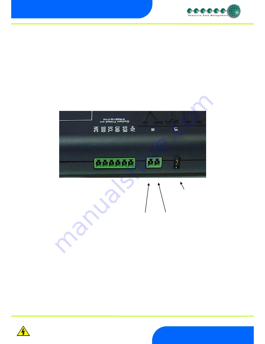
Ensure the transducer is correctly connected and the jumper is in the Pressure position.
Once the Switch has been correctly setup, it will pass values to each of the controllers connected to ports 1 through 10. In an EEV
application the evaporator in temperature probe reading for a case controller can be obtained from the ML Switch on which the controller
is connected. A suction pressure transducer is connected from the case Island to the 4-20mA input of the ML Switch and the pressure
read from this transducer is converted to a temperature based on the gas type being used by the system. This temperature is transmitted
to each controller connected to the switch and along with the suction temperature probe local to the controller the superheat is calculated.
Please see the ML Case controller user document from the RDM website for further details. (P-15 Minimum valve opening) We
recommend that this parameter be set to 0% when using ML Pressure Hub to calculate Superheat. Please note that RDM recommended
that the evaporator in temperature probe is fitted as the controller will use this to calculate the superheat in the event of a communication
loss with the ML Switch. The ML Case controllers require to have P14 (Evaporator control) set to 1 (Remote) for this feature to function
correctly.
Transducer Connection
MOP - Maximum Operating Pressure
When the MOP alarm is created a valve off command is sent to the ML controllers connected to the ML Switch. The percentage that the
valve shuts down to is dependent on the “Div Value” parameter in the ML case controller. When the ML Switch generates the MOP alarm
the controller reduces the maximum valve opening to this percentage. For example if the Div Value” parameter is set to 50% and the
MOP alarm is generated then the maximum valve opening will be limited to 50%. Therefore as the controller pulses the valve the
maximum the valve will open to is 50%.
If ML controllers are connected to the Switch then the LLV will be closed when the MOP alarm is created and return to normal operation
when the alarm clears. When the pressure reduces below the MOP diff the valves will revert to normal operation at 1 minute intervals.
The number of controller coming back to normal operation per minute depends on the “recovery count” value.
+12V loop feed
mA loop return
mA input selector


