background image


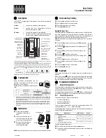
Reference to the icons: 

Schedule period 

Summary of Contents for Honeywell Home T6H700RW5001

Page 1: ...back to the user installer High LCD Contrast and backlighting for easier viewing in all light conditions Time out screen with selectable brightness Heating control Factory programmed daily or 5 2 default schedule Schedule with up to 6 independent time and temperature pairs to suit the comfort needs Hold until temperature override of programmed schedule temperature till the next switch point Schedu...

Page 2: ...Reference to the icons Schedule period 2 ...

Page 3: ...es Dimensions 49 x 52 x 27 mm w x h x d IP class 30 RF communication RF operation band ISM 868 0 868 6 MHz 1 duty cycle Max power 25mW Protocol Encrypted Comm Range 30 m in a residential building environment Comm technology short high rate transmissions to minimise air time and avoid collisions Receiver class R E D RX Cat 2 ETSI EN300 220 1 version 1 3 1 RF binding method Factory pre bound Wi Fi I...

Page 4: ...ycle Hour Minimum ON time in minutes Note a To change Cycle Hour b To change Minimum ON Time Heating Gas Boilers 30KW 6 1 No action required Oil Boiler 3 4 1 Set Minimum ON Time to 4 minutes 2 Set Cycle Hour to 3 Thermal Actuator 12 1 Set Cycle Hour to 12 Zone valve 6 1 No action required Special Features Description System Type When bound to a 2 channel receiver box the system type can be set Hea...

Page 5: ...ted in a hot cold location and cannot be moved because of wiring then the measured displayed temperature can be adjusted by 1 5 oC This feature is useful if the homeowner wants the reading to match another appliance temperature display Binding Menu to bind the Thermostat and the Receiver box test the RF signal strength of the radio communication and to clear an existing binding Reset Menu to reset...

Page 6: ...T6RWP THERMOSTAT PACKAGING ACC900 IN WALL POWER MODULE 6 ...

Page 7: ...ld not be placed near draughts in direct sunlight or near heat sources It should be at least 1 2 1 5 meters from the floor Needed during installation Wall box with minimum depth of 40 mm and with 230V cabling neutral and line An installed Receiver Box single or 2 channel version C Wall plate Using a screwdriver open wall plate terminal cover to connect wires B Power module Connect the 230V power w...

Page 8: ...row Now bind with the Receiver box Press the big button on the Receiver Box for 3 seconds Press to bind the thermostat to the Receiver Box When binding is successful Thermostat will show SUCCESS First Receiver box status LED will show green Press to continue the set up When bound to a 2 channel Receiver box the system type can be selected Press to set up system type Touch to finalise setup to setu...

Page 9: ...ct BIND and the signal will be sent 5 When binding is successful Thermostat will show SUCCESS First Receiver box status LED will show green Note When the Receiver box has been bound before first press with a small pin the pinhole for approximately 3 seconds to reset the binding All LED s will flash amber for a moment When binding is NOT successful Thermostat will show FAILED Receiver box will exit...

Page 10: ...o communication from the thermostat RF signal is blocked due to the location of the thermostat Receiver box is no longer powered RF communication might be too far or is blocked due to the location of the Thermostat or Receiver box Check the power to the Receiver box RF SIGNAL OFRECEIVER BOX LOW There is a weak radio signal from the Receiver box Try to move thermostat or Receiver box closer or re l...

Reviews: