background image

Tactical ResQmax Operation Manual

27

Care of the Projectile

The Projectile can be used over and over again if cared for properly.  Any visible damage to the 

Projectile is cause for immediate replacement.  

DO NOT ATTEMPT TO REFILL A DAMAGED 

CYLINDER

.  This may cause an accident resulting in serious bodily injury or death (refer to page 

17, section “Protecting the Cylinder/Projectile”).

After use and before filling again to be stored, the Projectile Cylinder and the Nozzle Assembly 

should be separated and maintained. The Projectiles should not be filled until the steps below 

are taken.  Regardless of whether the equipment was used in fresh or salt water, there will be 

residue in the cylinder that may give rise to corrosion if not thoroughly rinsed.

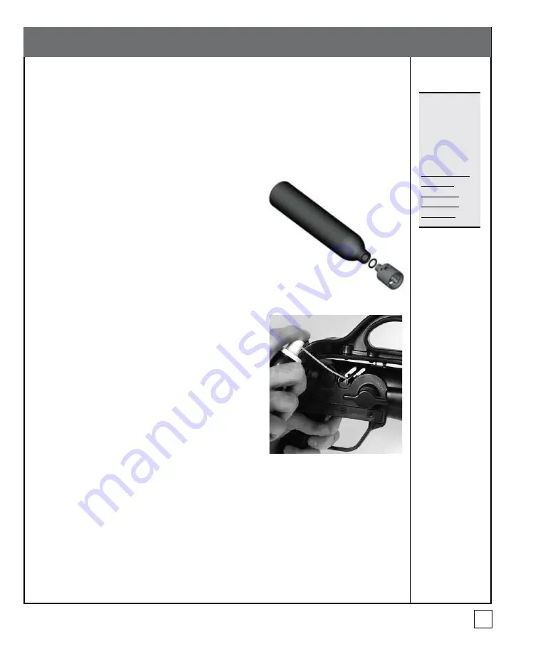
Figure 25a - 

Cylinder and Nozzle Assembly

1.  Unscrew the Nozzle Assembly from the Projectile 

Cylinder by turning it in a counter-clockwise direction 

(Fig. 25a).

2.  Thoroughly flush both parts with fresh water, shake 

out excess water, and let air dry. 

3.  Inspect the Projectile Cylinder and the Nozzle for any 

damage or corrosion.

4.  Once dried, lubricate the threads on the Nozzle Assembly 

with Corrosion Block and screw the Nozzle Assembly 

back into the Projectile Cylinder in a clockwise direction 

until hand tight (Fig. 25a). DO NOT OVERTIGHTEN. 

DO NOT use any sealant or tape on the threads of the 

Nozzle. Corrosion Block can be used on any part of the 

Projectile.  Each Projectile Cylinder is intended to have 

a maximum service life of five years from the date of 

manufacture  and  must  be  removed  from  service  at 

that time or sooner if there is any visible evidence of 

damage. Each Projectile Cylinder is date stamped. It is the 

responsibility of the purchaser to ensure that the Projectile 

Cylinder is not used after the service life has expired.

Figure 25b - Lubrication of Mechanism 

with Corrosion Block

Care of the Launcher

The Launcher has a stainless steel Mechanism. The Launcher should be rinsed after all maritime 

operations in order to keep corrosion to a minimum. Corrosion Block should be used as a 

lubricant on the Outer Ring of the Launcher Mechanism by reaching in through the vent holes 

on the Launcher (Fig. 25b).  If a Projectile Cylinder containing residual water is pressurized and 

launched, the Mechanism O-ring can become dislodged. If there is an audible air leakage when 

the Projectile is loaded into the Launcher and the Valve Key is used to open the Projectile Valve to 

pressurize the system, check if the Launcher Bleed Screw is properly tightened (refer to page 16). 

If the Launcher Bleed  Screw is closed and the leakage persists, the Mechanism O-ring should be 

checked and replaced if necessary; please contact the Manufacturer for instructions or service.

Maintenance

Note: 


Inexpensive 

replacement 

Projectile 

Cylinders are 

readily available 

from the 

Manufacturer. 

DO NOT USE 

a visibly 

damaged 

Projectile 

Cylinder!


Summary of Contents for Tactical ResQmax

Page 1: ...Operation Manual The Global Leader in intrinsically safe line throwing equipment INC R E S CUESOLUTI O N S I N TERNATION A L ResQmaxTM the NEW Generation TACTICAL...

Page 2: ...s or property are in the vicinity of the target The Tactical ResQmax requires proper training and servicing If you are not familiar with this equipment or are unwilling to follow the recommendations a...

Page 3: ...ncher 11 Extending the Folding Stock 11 Collapsing the Folding Stock 11 Connecting the Launcher to the Line Container 12 Disconnecting the Launcher from the Line Container 12 Operating the Safety Push...

Page 4: ...Climbing Grappling Hook for Deployment 24 Deployment 26 Deploying the Tactical ResQmax 26 Maintenance 27 Care of the Projectile 27 Care of the Launcher 27 Replacing the O Rings in the Nozzle Valve 28...

Page 5: ...is Tactical ResQmax Operation Manual and accompanying Training CD prior to first use Applications Some applications of the Tactical ResQmax include Messenger Line Deployment Ship to Ship Line Deployme...

Page 6: ...is not reusable and must be replaced if it should ever fail A second Pressure Relief Assembly is installed on the Launcher Mechanism and is active at all times when the Mechanism is pressurized A spar...

Page 7: ...perator s ability to aim the Projectile more accurately Fig 2 When in the folded position the Folding Stock becomes a convenient carrying handle Fig 1 Figure 1 Launcher right side view Figure 2 Launch...

Page 8: ...ied with each Tactical ResQmax to permit charging from multiple air sources if required ResQmax Tool Kit 990 TheoptionalResQmaxToolKit Fig 4 providesallthetoolsneededforoperationalmaintenance of the T...

Page 9: ...iding protection for the projectile and reducing projectile bounce on contact Luminescent Training Projectile 306 S Fig 5b has factory installed luminescent protective cover which combines the best fe...

Page 10: ...r Cordura fabric with two external zippered pockets one internal zippered pocket and a weatherproofmembraneovertheentirefootprint Fig 8 Figure 9 Pelican Transport Storage Case 908 Minimum Weight Part...

Page 11: ...Fig 9a Step 2 The Stock Catch Plate will automatically engage and lock the Folding Stock in the extended position Collapsing the Folding Stock To collapse the Folding Stock for use as a handle follow...

Page 12: ...oth the front and rear grooves of the Line Container simultaneously Push firmly forward until the Line Container Catch on the Launcher automatically engages in the locking hole in the Line Container F...

Page 13: ...ety Push Knob to the OFF position immediately before firing the Launcher When the safety is in the OFF position the Safety Push Knob remains recessed inside the cavity about 6 mm Fig 11b After firing...

Page 14: ...zzle Protector upward while keeping the Bridle Lines tight and uncrossed along each side of the Projectile Rotate the Projectile as necessary until you feel the V groove engage with the Mechanism Fig...

Page 15: ...e rotate the Valve Key 90 in a clockwise direction Fig 14 Step 2 After rotating full 90 release the Valve Key allowing it to extend fully and disengage from the Nozzle Valve Fig 13a Opening the Nozzle...

Page 16: ...red operating pressure is achieved 4 Rotate the Bleed Screw Handle in a clockwise direction to stop the escape of air The second purpose of the Bleed Screw is to permit the operator to bleed off the p...

Page 17: ...ted for damage Damaged Protectors should be replaced to protect the Projectile Cylinder Figure 17a Projectile Protector Figure 17b Damaged Training Projectile Cover Figure 17c Damaged Projectile NOTE...

Page 18: ...rojectile to be filled If the Valve Key is in line with the flow of air then the Valve is OPEN Fig 18a To charge the Projectile follow these steps 1 Connect the appropriate Filler Hose Adapter to the...

Page 19: ...erpendicular to the flow of air Fig 18g Always replace the Filler Hose Wrench back in the retainer on the Filler Hose 10 Next locate the drain port adjacent to the red Bleed Screw on the Filler Block...

Page 20: ...is being maintained CAUTION IftheProjectilesaresubjectedtoextremeheat thepressurecouldrise sufficientlytorupturethePressureReliefAssemblyallowingtheairtoescapeand temporarily preventing use of the equ...

Page 21: ...1 Disengage the Safety Assembly by pressing the Safety Push Knob 2 Pull the Trigger to release the Projectile into your hand or the ground With pressure indicated on the Launcher Pressure Gauge If yo...

Page 22: ...hedoor open toward you 2 Allow12inches 30cmofthe deadend oftherope fitted with the snap shackle to hang freely outside of the right side of the Line Container Fig 19a and begin dropping the line insid...

Page 23: ...Cut Away Pin holds the Line Container Door closed until deployment automatically releasing the door of the Line Container to allow the line to follow the Projectile without resistance Climbing Lines a...

Page 24: ...ll the Grappling Hook over the end of the Projectile Align the V groove of the Nozzle Protector at 90 to the Eyelet of the Grappling Hook to keep the Line oriented correctly Fig 23b 3 RuntheLinealongt...

Page 25: ...8 Re engage the Cut Away Pin to fasten the Line Container Door closed 9 Using the Quick Link on the Bridle Lines attachtheBridleLinestotheloopcontaining the Cut Away Pin on the Line Fig 23f 10 Connect...

Page 26: ...t and are too short to deploy horizontally at full service pressure A Climbing Line deployed horizontally at full service pressure will reach full extension in approximately one second and apply a con...

Page 27: ...e Corrosion Block can be used on any part of the Projectile Each Projectile Cylinder is intended to have a maximum service life of five years from the date of manufacture and must be removed from serv...

Page 28: ...e Body 3 Remove the Nozzle Plug Retaining Clip from the Nozzle Valve Plug using Retaining Clip Pliers 4 Push the Nozzle Valve Plug out of the Nozzle Body Lower O ring 60405 Nozzle Valve Retaining Clip...

Page 29: ...ervice or performance Figure 27 Nozzle Valve Plug Face O ring 60406 Upper Lower O rings 60405 Installing the Nozzle Plug Valve O rings with the Installation Tool 1 Remove and discard the Upper Lower a...

Page 30: ...damage 4 Reinstall the Pressure relief Assembly Fig 26 pg 28 6 Slide the Nozzle Protector over the Nozzle Body taking care to ensure that the aligning notch on the Nozzle Body is engaged with the matc...

Page 31: ...iring and each discharge of a Cylinder Nozzle Assembly The Manufacturer recommends that this equipment be serviced by technicians trained and certified by the Manufacturer in the maintenance and repai...

Page 32: ...e in service However units subjected to more frequent use such as training programs demonstration equipment and equipment used as a tool in commercial applications on a frequent or daily basis or unit...

Page 33: ...the Nozzle Valve If the Pressure Gauge shows pressure then it is charged and you may proceed to shoot or close the Nozzle Valve and remove the Projectile It is a good idea to develop a system to ensur...

Page 34: ...c distributor for assistance When you prepare to fire the Launcher the Mechanism is underpressure Ifyouapplystrongfingerpressureagainst theTrigger prior to releasing the Safety the air pressure in the...

Page 35: ...ns International Inc will repair or replace your Tactical ResQmax or otherwise notify you within 30 days of receipt of the Tactical ResQmax Any actions for breach of warranty or breach of contract mus...

Page 36: ...lon 165 50 7 1 5 780 2 622 4 3 2 802 HMPE and Nylon 330 100 5 5 1 3 200 1 194 5 2 2 6 803 Spectra 500 152 4 1 1 500 680 1 75 0 8 804 Spectra 500 152 6 1 3 000 1 360 3 5 1 6 805 Dacron 500 152 3 1 500...

Reviews: