


9
u
Release CAL button.
u
Check the ‘Readhead mounting/installation’ and recalibrate the system.
NOTE: System must be recalibrated after restoring factory defaults.
Switching Automatic Gain Control (AGC) on or off
AGC can be switched on or off via the interface.
u
Press and hold the CAL button on the interface for >3 seconds to switch AGC on or off. The CAL LED on
the readhead will be illuminated when AGC is active.
NOTE: The system must be calibrated before switching AGC on.
System calibration
Calibration is an essential operation that completes readhead set-up, with the optimum incremental
and reference mark signal settings stored in the readhead’s non-volatile memory.
Before system calibration:
u
Clean the scale and readhead optical window (contamination around the reference mark
may result in reference mark dephasing).
u
If reinstalling restore factory defaults.
u
Ensure Automatic Gain Control is switched off (CAL LED on readhead is not illuminated).
u
Maximise the signal strength along full axis of travel.
NOTE: CAL routine maximum speed <100 mm/s (all Ti/TD interface models).
TD interface can be calibrated in either resolution.
Step 1 – Incremental signal calibration
u
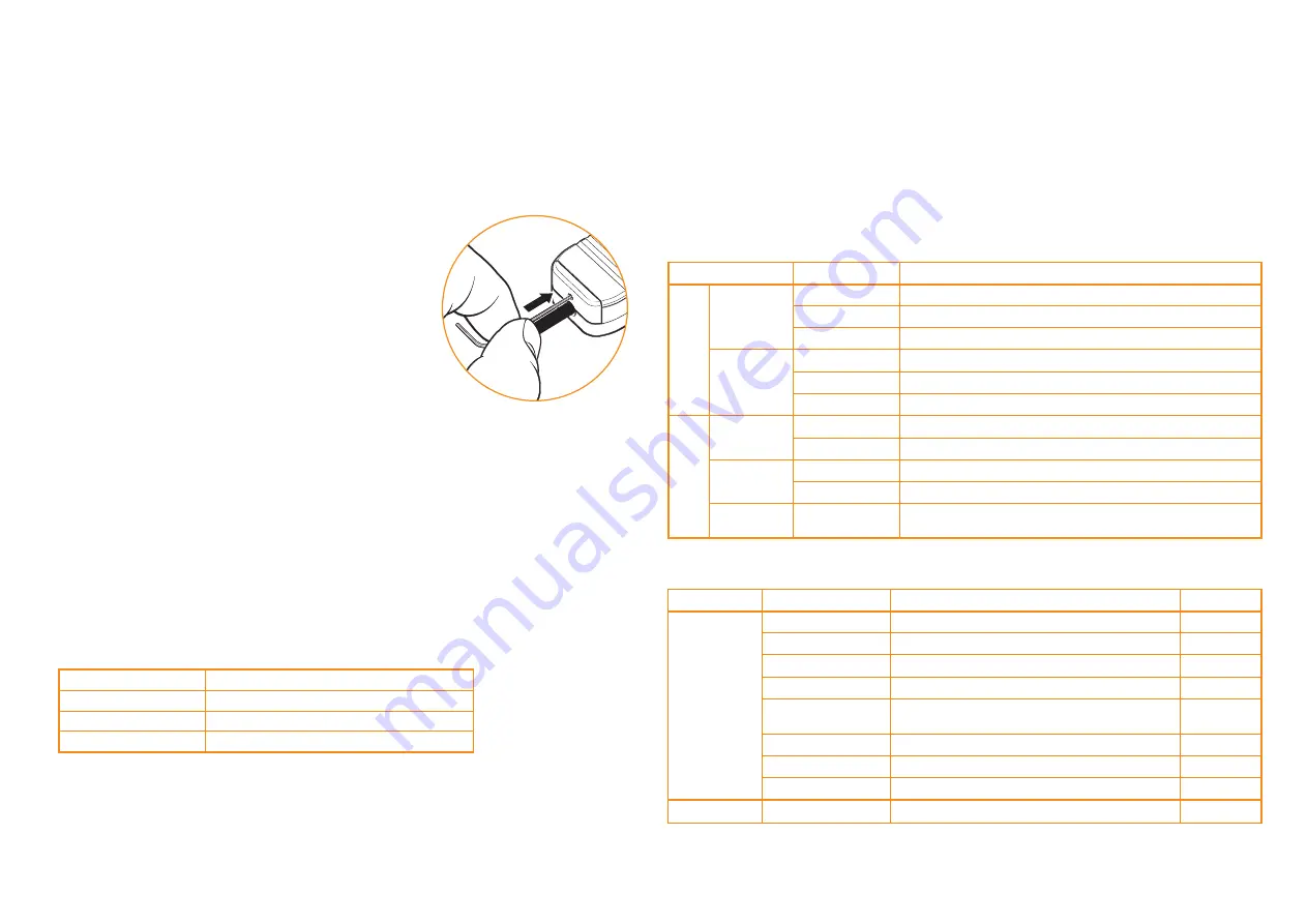
Press the CAL button on the end of the interface for <2 seconds using
a 2 mm allen key or similar tool.
WARNING! Activating the CAL switch only requires 2.5 N force.
Applying excess force may permanently damage the switch.
u
The CAL LED will now periodically single-flash to indicate that
it is in incremental signal calibration routine.
u
Move the readhead along the axis, ensuring you do not pass
the selected reference mark until the CAL LED starts
double-flashing. This indicates the incremental signal is now
calibrated and the new settings are stored in the readhead memory.
u
The system is now ready for reference mark phasing.
u
For systems without reference mark, go to ‘Calibration routine - manual exit’
u
If the system does not automatically enter the reference mark phasing stage (no double-flashing of the
CAL LED) the calibration of the incremental signals has failed. After ensuring failure is not due to overspeed
(>100 mm/s), exit the calibration routine, restore factory defaults and check the readhead installation and
system cleanliness before repeating the calibration routine.
Step 2 – Reference mark phasing
u
Move the readhead back and forth over the selected reference mark until the CAL LED stops flashing
and remains off. The reference mark is now phased.
NOTE: Only the chosen reference mark that has
been used in the calibration routine is guaranteed to remain phased.
u
The system automatically exits the CAL routine and is ready for operation.
u
If the CAL LED continues double-flashing after passing the chosen reference mark many times,
it is not detecting the reference mark. Ensure that the correct readhead configuration is being used.
Readheads can either output all reference marks or only output a reference mark where
a reference selector magnet is fitted.
Calibration routine – manual exit
u
The calibration routine can be exited at any stage. To exit the calibration routine press the CAL button.
On successful exit the CAL button will stop flashing.
Restoring factory defaults
When realigning the readhead, reinstalling the system or in the case of continued calibration failure,
factory defaults should be restored.
To restore factory defaults:
u
Switch system off.
u
Press and hold the CAL button whilst switching the system on. The CAL LED on the readhead will flash
several times indicating that the factory defaults have been restored.
Ti0004 to Ti20KD and TD4000 to TD0040 Interface LED diagnostics
Normal set-up; signal level 110% to 135%
Optimum set-up; signal level 90% to 110%
Normal set-up: signal level 70% to 90%
Acceptable set-up; signal level 50% to 70%
Poor set-up; signal may be too low for reliable operation;
signal level <50%
Poor set-up; signal level <20%; system in error
Over speed; system in error
Over signal; system in error
Reference mark detected (speed <100 mm/s only)
Status
Signal
Alarm output*
Indication
Incremental
Reference mark
Purple
Blue
Green
Orange
Red
Red / blank - flashing
Blue / blank - flashing
Purple / blank - flashing
Blank flash
No
No
No
No
No
Yes
Yes
Yes
No
* Alarm output will take the form of 3-state or line driven E- signal depending on interface configuration.
Also, some configurations do not output overspeed alarm. See product nomenclature for details.
-Momentary status only, while fault condition remains.
-Alarm may result in axis position error, re-datum to continue.
T100
x
readhead LED diagnostics
Normal set-up: signal level >70%
Acceptable set-up; signal level 50% to 70%
Poor set-up; signal may be too low for reliable operation; signal level <50%
Normal phasing
Acceptable phasing
Poor phasing; clean scale and recalibrate if required
Automatic Gain Control – On
Automatic Gain Control – Off
Calibrating incremental signals
Calibrating reference mark
Restore factory defaults
Status
Set-up
CAL
LED
Indication
Incremental
Reference mark
Operating
Calibration
Reset
Green
Orange
Red
Green (flash)
*
Orange (flash)
Red (flash)
On
Off
Single flashing
Double flashing
Flashing at
power-up (<2s)
*Flash will effectively be invisible when incremental signal level is
>70% when passing reference mark.
CAL LED
Single flashing
Double flashing
Off (auto-complete)
Settings stored
None, restore factory defaults and recalibrate
Incremental only
Incremental and reference mark
TONiC RGSZ installation guide