RSLM high accuracy linear encoder
Installation guideM-9653-9154-05-B
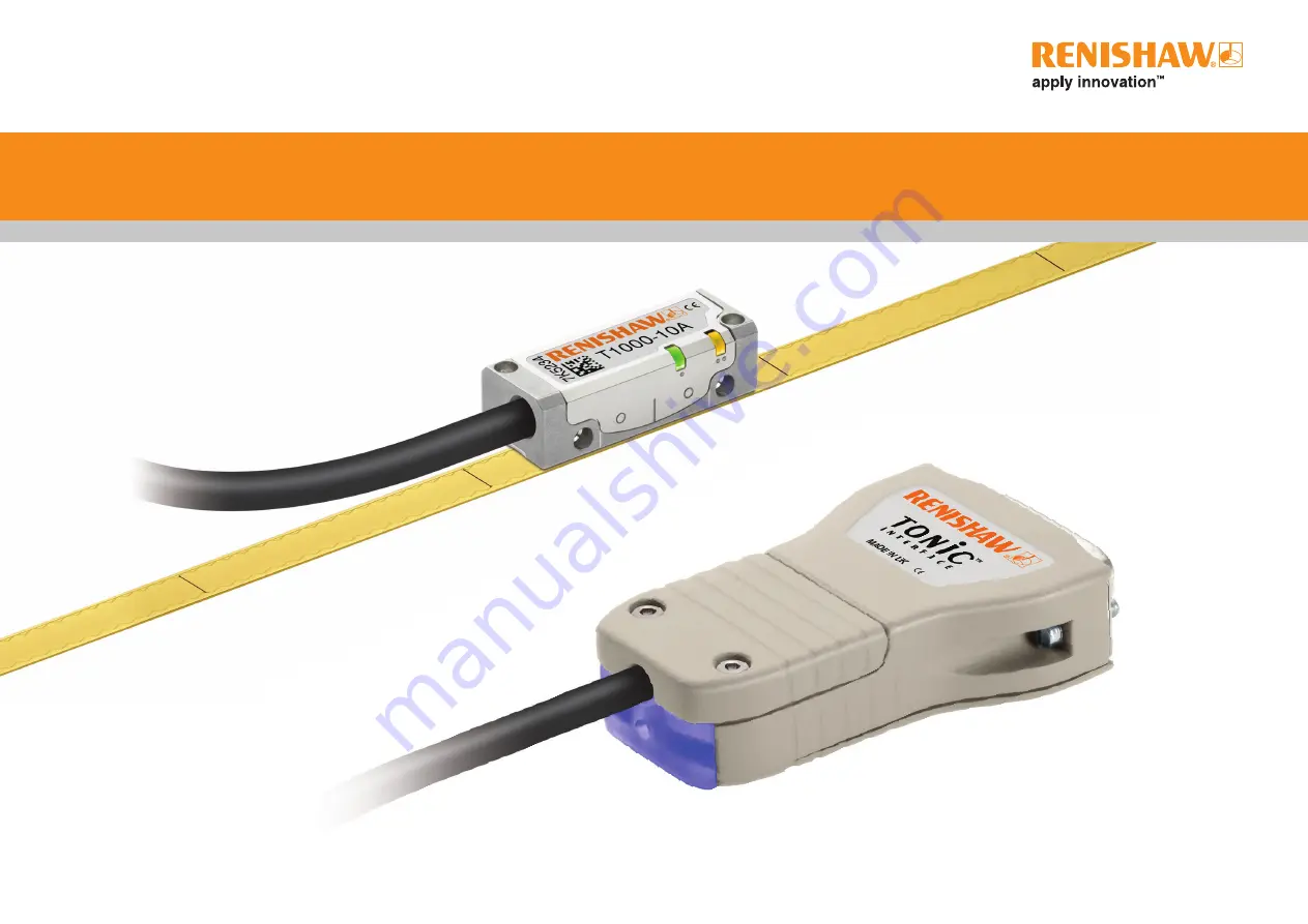
TONiC T100x RGSZ linear encoder system
Page 1: ...RSLM high accuracy linear encoder Installation guide M 9653 9154 05 B TONiC T100x RGSZ linear encoder system...
Page 2: ...ication 5 End clamps 5 TONiC interface drawing 6 TONiC quick start guide 6 System connection 7 Readhead mounting and alignment 8 Reference mark selector and limit magnet installation 8 System calibrat...
Page 3: ...oHS Patents Features of Renishaw s encoder systems and similar products are the subjects of the following patents and patent applications EP0748436 US5861953 EP1173731 US6775008B2 JP4750998 CNCN100543...
Page 4: ...nstall scale within 18 months of manufacture date Humidity 70 C 0 C Operating 2 Storage 70 C 20 C UHV readhead Bakeout 120 C 95 relative humidity non condensing to EN 60068 2 78 Methylated Spirits Ace...
Page 5: ...ius R 10 Static bend radius 4 2 5 0 2 5 Set up LED CAL AGC LED A 0 6 Pitch tol 1 35 23 11 5 6 min 18 16 7 8 7 8 2 off mounting holes M2 5 through counterbored 3 x 2 75 deep from alternative mounting f...
Page 6: ...ition at extent of travel RGSZ20 S 6 05 0 1 RGSZ20 P 6 2 0 1 Q limit magnet Nominal Q limit trigger point 3 20 0 5 0 2 100 F Reference mark selector magnet Reference mark spacing 50 30 Ra 3 2 13 End c...
Page 7: ...temporarily hold the end clamp in position while the glue cures Remove the backing tape from either side 1 5 m m 1 Remove the lacquer coating from the last 15 mm of each end of the scale with a knife...
Page 8: ...until the CAL LED on the readhead switches off Install and align the readhead to maximise signal strength over the full axis travel as indicated by the readhead and interface set up LEDs readhead Gre...
Page 9: ...head screws 2 Taking care not to touch the pins plug the connector into the socket in the interface ensuring correct orientation as shown 3 Refit the cover plate ensuring the cable ferrule is located...
Page 10: ...the readhead and be sufficiently stiff to prevent deflection or vibration of the readhead during operation Readhead set up Ensure that the scale readhead optical window and mounting face are clean and...
Page 11: ...AL routine and is ready for operation u If the CAL LED continues double flashing after passing the chosen reference mark many times it is not detecting the reference mark Ensure that the correct readh...
Page 12: ...connected Case 5 V Power 5 V Sense 0 V Power 0 V Sense Vp Vq VX CAL Inner shield Outer shield V1 V2 V0 Interface Ti0000 NOTE TD maximum speeds are resolution dependent as defined above Output connect...
Page 13: ...Field Ground The inner shield should be connected to 0 V at receiving electronics only Care should be taken to ensure that the inner and outer shields are insulated from each other If the inner and o...
Page 14: ...tor P Q Active high or Active low P Q Repeatability 0 1 mm Length of limit actuator Incremental 2 channels A and B in quadrature 90 phase shifted Reference NOTE No limits on TD interfaces P limit beco...
Page 15: ...adius UL recognised component UHV Tin coated braided single screen FEP core insulation Maximum cable length Readhead to interface 10 m Interface to controller Renishaw encoder systems have been design...
Page 16: ...site at www renishaw com contact M 9653 9154 05 RENISHAW and the probe symbol used in the RENISHAW logo are registered trade marks of Renishaw plc in the United Kingdom and other countries apply innov...