20
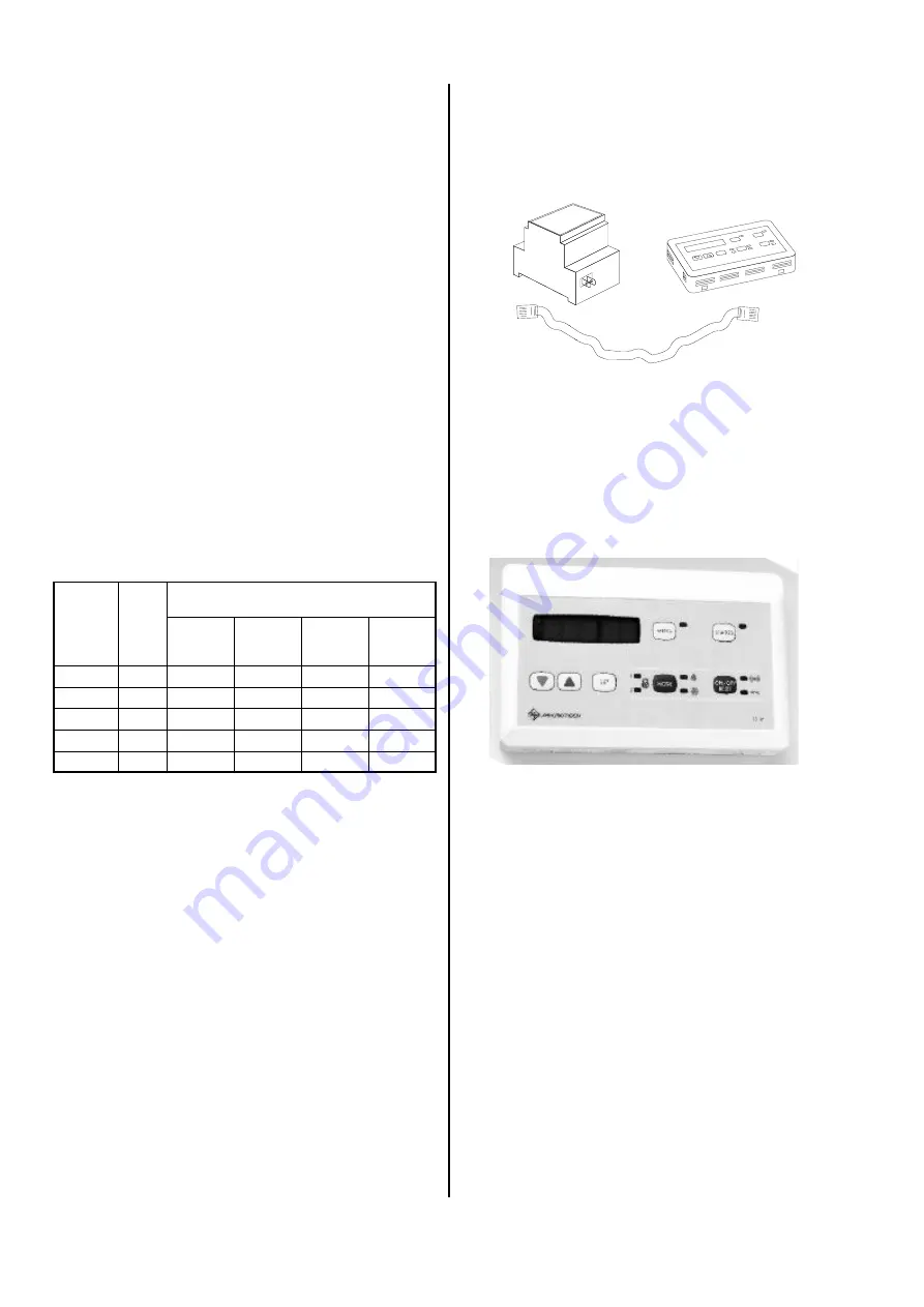
Electrical connection of the cable remote control
The remote control comes with an operating module
TS-W, the additional regulation module CS-DIN/TTL
and an interface line.
Cable Remote Control
The cable remote control can be purchased as an ac-
cessory. It is used to query and program the chiller from
a remote location.
In the factory, all models are programmed using the re-
mote control.
Install the remote control as follows:
1) Place the two, two wire connection lines between the
location where the remote control is to be assembled
and the switch box of the chiller. The minimum
cross-section is Cu 1.5 mm². The max. current may
not fall below 2 %.
2) Remove the assembly back panel of the operating
module and attach it to the setup location.
3) Clamp the lines to the terminal strips of the elec-
tronic board and make sure that the polarity is cor-
rect. Lock the operating module into place in the as-
sembly back panel.
4) Insert the additional module into the switch box of
the chiller.
5) Clamp the lines to the terminal strips of the previ-
ously mounted additional regulation module in the
switch box of the chiller.
6) Using the interface line, you can connect the addi-
tional regulation module and the CH–DIN regulation.
7) Test the function of the remote control.
Percent-
age of
ethylene
glycol
Correction factors when using a brine
made of ethylene glycol * and water
Cooling
capacity
Power
consump-
tion
Flow rate
Pressure
loss
Vol. %
°C
K
L
K
PE
K
V
K
D
0
0
1
1
1
1
20
-11
0.96
0.995
1.04
1.19
34
-20
0.95
0.990
1.09
1.35
40
-25
0.925
0.985
1.105
1.51
Anti-
freeze
* We recommend an ethylene glycol with inhibitors as
corrosion protection, e.g. antifreeze N or L.
Where the heat medium comes into contact with
drinking water or food, antifreeze L is to be given
preference because it contains the physiologically
harmless substance 1.2 propylene glycol.
The data provided in the table refers to antifreeze N.
Antifreeze L has other correction factors and thus a
different pressure loss!
Antifreeze to prevent freezing
During cold seasons of the year, it is possible that the
water in the chiller will freeze at temperatures below 0°C
which can cause damage, for example, to the plate heat
exchanger. The same applies to installed connection
lines and system parts in rooms not susceptible to frost.
For this reason, we recommend mixing the water with
an adequate amount of antifreeze (e.g. antifreeze N).
If brine (a mixture of water and frost protection) is not
used in the hydraulic cycle, the water is to be drained
from the system parts in areas susceptible to frost dur-
ing non-operation in the winter.
Appropriate shut-off and drainage mechanisms are to
be used. The amount of water drained out must be re-
filled before the next cooling season begins.
If the chiller is to be used throughout the whole year, e.
g. to air-condition a computer room) the hydraulic cycle
must be operated with brine.
When using brine, you must make sure that the pres-
sure loss increases as a result of the changing density
in the hydraulic cycle. Whether or not to use brine must
be considered when the hydraulic cycle is being set up.
The variable technical data can be found in the table be-
low:
The operating module is to be mounted in the desired
location. The operating module is connected to the
RKW with two, two-wire lines with a maximum length of
50 m. One line is used to transfer data and the other to
supply the current 12 V~ of the operating module. It is
not necessary to use an additional transformer.
The programmed data is transferred to the CH– DIN
regulation by an interface line.
CS-DIN/TTL
TS-W


