background image

IM 812 / Page 8 of 28

Electric Subbase
An electrical subbase is optional for 208V and 230V units, but
is standard for 265V units. It is available in two sizes: 3˝ or 4˝.
The subbase contains leveling legs for adjustment of up to 1˝
additional height. Install the wall sleeve and subbase at the
same time.
Note: A minimum of 4

3

8

˝ of the wall sleeve must project

into the room when using a subbase.

Installation
1.

If the minimum depth subbase is required (4

3

8

˝ ), discard

the side extension pieces. The subbase always mounts
flush with the front of the wall sleeve.

2.

If more than the minimum depth subbase is required, de-
termine the depth of the side extension pieces desired
and break at the proper score-line. Insert the side exten-
sion pieces into the front assembly and secure with two
short black screws at each side.

3.

Insert leveling legs into subbase bottom flanges. Four (4)
legs will be needed if side extensions are used. Only two
(2) will be required if side extensions are not used.

4.

Place the subbase on the floor and align its center line
with the center line of the wall opening. Do not fasten the
subbases to the floor. After the wall sleeve has been in-
stalled, attach the subbase to it using the two clips
provided. Adjust the subbase height so it rests tight against
the bottom of the wall sleeve.

5.

The wiring should be roughed in and the conduit connected
to the electrical junction box. Complete the installation by
wiring the receptacle to the incoming power supply.

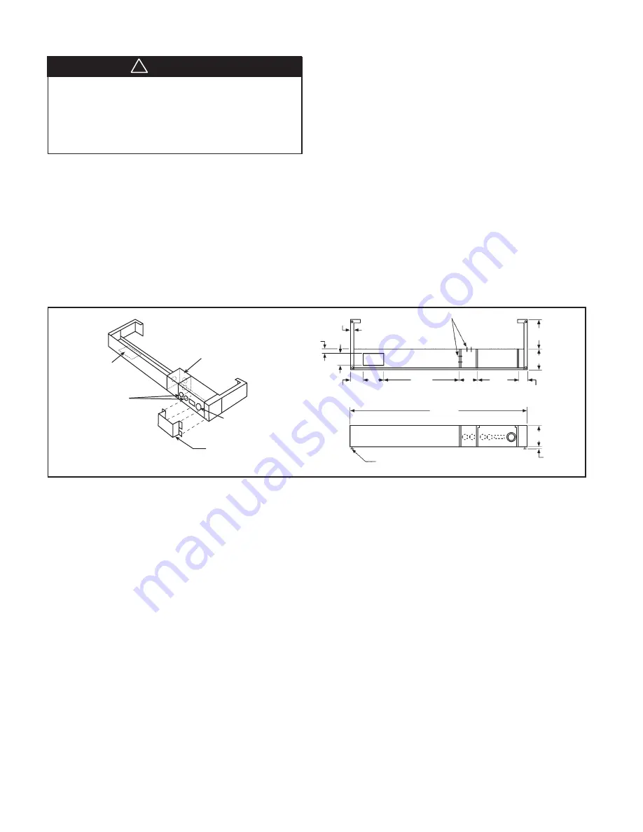
Subbase Installation

Figure 5. Electric Subbase

Electrical
Junction
Box for Main
Power Connection

Receptacle
Mounting Location

Plug/Cord Cover
(Required on 265V Units Only)

Knockouts for

Optional Fuse &

Disconnect Switch

Electrical Knockouts

3" or 4"

0" to 1"

41

1

2

"

Leveling Leg

17"

12"

5"

2

1

2

"

0" to 9

3

8

"

4

3

8

"

1

1

2

"

7

8

"

5

8

"

3"

Plan

Front Elevation (Three Front Panels in Place)

3

" x 5"

Opening for
Electrical and/or
Drain Rough-In

Side
Extension
Piece

3

1

2

"

All wiring must be done in accordance with local and National
Electrical Code requirements. Some units have a multitap
heater, so the Kw is determined by the field-installed power
cord, and some have factory installed cords with fixed heat-
ers. Refer to the data plate for proper overcurrent protection.
Time delay fuses or HACR circuit breakers are required to avoid
nuisance tripping.
Power Supply Wiring
208V and 230V units use a power cord that exits from beneath
the conditioner on the control (R.H.) side. The cord has a usable
length of 60˝ from where it exits the conditioner. (Do not use
extension cords.) When a subbase is not used, the receptacle
is generally mounted beneath the conditioner or on the wall
beside it (208-230V only). An electrical subbase is available
and contains a junction box for a field-mounted receptacle.
All electrical connections are made within the subbase, thus
eliminating the need for a wall-mounted receptacle (see Fig-
ure 5). The subbase is available in 3˝ or 4˝ height and can be
furnished with a factory-mounted fused disconnect and re-
ceptacle as an option. The subbase is optional for 208V and
230V, but mandatory for 265V. The 265V chassis uses a “short
cord,” which is just long enough to plug into the subbase. A
plug/cord cover is also required on 265V to make the power
cord inaccessible without the use of tools, (see Figure 5).

Power Supply and Control Wiring

Control Wiring
If the unit control pad will be wall mounted, rough in the 35´ or
50´ low-voltage wire harness at this time. The end of the har-
ness, with exposed terminals (the larger black connector), will
plug into the control box at the unit. The other end (smaller
white connector), with concealed terminals, will connect to
the PC board in the control pad on the wall. At the unit, exit
the wall with enough wire harness to reach the CN5 recep-
tacle behind the access cover on the control box front. At the
control pad mounting location on the wall, exit with only a few
inches of wire harness. Route the wire harness through the
opening in the control pad mounting plate and secure the plate
to the wall. Unplug the short cord from the PC board in the
control pad and discard. Plug in the new wire harness from
the wall and snap the control pad onto the mounting plate.
The harness should all be concealed behind the control pad
when finished. If an optional 24V wall stat will be used rather
than the control pad, rough in the 4 to 7 low voltage wires as
required by the stat. If remote ON/OFF control will be used,
rough in 2 low voltage wires (22 ga. min.) to a maximum of
325´ from the unit, (see page 4.) If unit will be connected to a
motion sensor and door switch, rough in the 4 low voltage
wires for the motion sensor and the 2 low voltage wires for the
door switch. Leave enough wire at the unit to reach the recep-
tacles behind the access cover on front of control box.

WARNING

!

All electrical work must be done by trained, experienced
electricians in accordance with applicable codes and stan-
dards. Kinked, bent or chaffed cords; improper ground-
ing or fusing; improper current or voltage; or improper
installation can cause fire or electric hazards that can re-
sult in property damage, personal injury or death.

Summary of Contents for IM 812-2

Page 1: ...Installation Maintenance Data IM 812 2 Group PTAC PTHP Date April 2006 McQuay Remington Packaged Terminal Air Conditioners and Heat Pumps C Vintage 2006 McQuay International...

Page 2: ...2 Wall Sleeve 3 Outdoor Louver 4 Subbase Optional for 208V and 230V units but manda tory for all 265V 5 Separate plug in power cord selects heater size NOTE Some units with fixed heaters are also avai...

Page 3: ...nal kW 30A Electric Heater7 Z 5 0 Nominal kW 20A 265V Electric Heater8 C Chassis Mounted Control9 W Wall Mounted Control10 Notes 1 All chassis ship with an Installation Manual and mounting screws 2 Fa...

Page 4: ...on the indoor fan will operate continuously When dip switch 8 is in the ON position the indoor fan will cycle on and off with the compressor or heater In cycle fan dip switch 8 ON the fan will start e...

Page 5: ...y using a G11 hand held remote con troller available from your sales representative Programming P1 using the G11 control press and hold the upper button for 3 seconds until P1 starts flashing on the G...

Page 6: ...e used to provide support over each opening The rough opening should measure 161 4 high x 421 4 wide see Figure 2 Note 2 When a subbase is used the opening must start 31 4 or 41 4 above the finished f...

Page 7: ...n using the outdoor drain kit the sleeve must be flush or beyond the outside finished wall do not recess Install the outdoor drain kit as follows 1 Assemble the drain kit as shown in Figure 4 2 Choose...

Page 8: ...60 from where it exits the conditioner Do not use extension cords When a subbase is not used the receptacle is generally mounted beneath the conditioner or on the wall beside it 208 230V only An elect...

Page 9: ...subbase or from other field supplied materials or it can be floor mounted for 208 230V Install as follows 1 Clean the opening of all debris that may interfere with installation 2 If the unit is to be...

Page 10: ...lace a thin pad of mastic on bottom of the opening and slide in the wall sleeve Be sure to recess the wall sleeve enough to accommodate outside louvers This recess is 3 8 for stamped louvers and 11 8...

Page 11: ...optional drain kit is to be employed heat pumps only refer to page 7 before proceeding 4 If wall thickness exceeds dimensions shown in Table 1 a wall sleeve extension must be used Install the extensio...

Page 12: ...the caulking does not block the weep holes 3 Attach indoor drain kit if used according to the instruc tions on page 7 Outdoor drain kits are not designed to be used with sleeve extensions Louver Fram...

Page 13: ...blade design that will not cause recir culation of condenser air Free area is defined by ASHRAE as the minimum area of the openings in an air inlet or outlet through which air can pass Have your local...

Page 14: ...the room The chassis weighs approximately 150 lbs Use blocking and lifting devices Do not raise over any body parts 1 Remove the shipping carton and inspect for any shipping damage Report any found t...

Page 15: ...located at the lower left end of the chassis See Figure 15 Note Remove shipping screw from door if it needs to be opened 4 If the conditioner will use the standard control pad continue to step 5 If a...

Page 16: ...the room and close the door Wait 6 minutes then re enter the room The unit should now show mode and temperature pro grammed for P1 Remove the short from the T SHRT prongs to restore the normal 15 minu...

Page 17: ...emoval Also see pages 5 and 8 2 If a subbase is used under the unit wall sleeve a small hole may be drilled and grommeted in the subbase front to allow passage of the low voltage wires 3 When using a...

Page 18: ...Disconnect all electric power including remote disconnects before servicing Failure to discon nect power before servicing can cause severe personal injury or death Use copper conductors only Unit term...

Page 19: ...age Disconnect all electric power including remote disconnects before servicing Failure to discon nect power before servicing can cause severe personal injury or death Use copper conductors only Unit...

Page 20: ...Voltage Disconnect all electric power including remote disconnects before servicing Failure to discon nect power before servicing can cause severe personal injury or death Use copper conductors only U...

Page 21: ...rce 2 Remove the front panel and clean it 3 Remove the chassis from the wall sleeve and move it to the maintenance department Replace it with spare chassis or weather plate 4 Check all seals and insul...

Page 22: ...and the temperature of the conditioned space is 80o F Figure 20 Refrigeration Cycle 80o F Room Air to Evaporator 45o F R22 Liquid and Gas to Evaporator Capillary Restrictor 120o F Condenser Air to Out...

Page 23: ...h condenser due to 1 Dirty condenser 2 Obstructed outdoor louver 3 Condenser fan not running 4 Condenser fan not up to speed 5 Condenser fan slipping on motor shaft 6 Recirculation of condenser air a...

Page 24: ...air flow 3 Clean or replace 4 Remove obstructions 5 Check motor 6 Check for correct voltage 7 Adjust blower wheel position and tighten set screw d Refer to original load calculations recalculate heat...

Page 25: ...Loose plug connec tion defective control pad or PC board a Replace b Replace c Replace d Clean coils fans or filters Replace fan motor Check baffles in sleeve extension Check free area of louver Repla...

Page 26: ......

Page 27: ......

Page 28: ...visit us at www mcquay com and click on training or call 540 248 9646 and ask for the Training Department Warranty All McQuay equipment is sold pursuant to its standard terms and conditions of sale i...

Reviews: