background image


UM-0206(1)


7 | P a g e


2.2


Recommended Operating Parameters


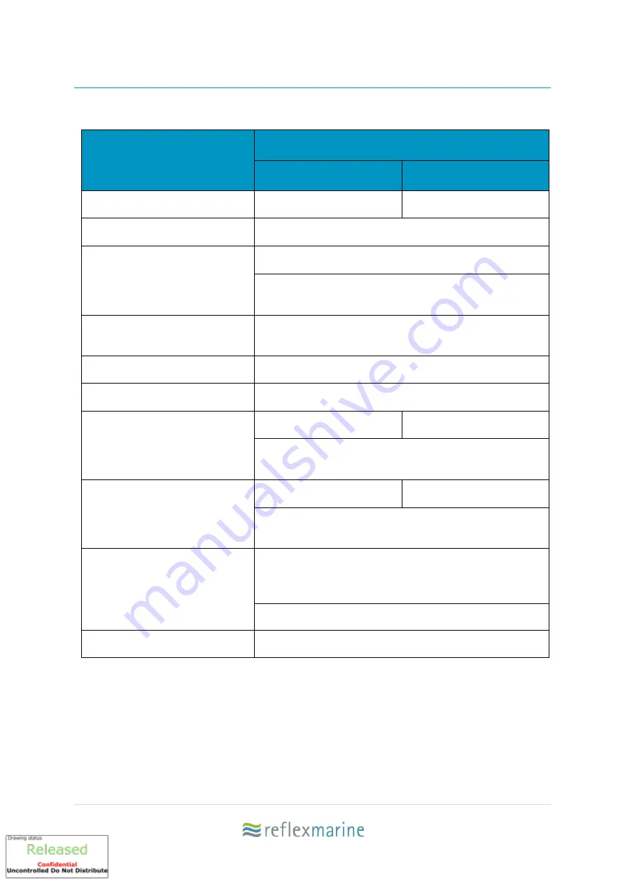
Table 3 Recommended Operating Parameters 

Parameter 

Recommendation 

XT4 + XT6 

XT10 

Vertical Impact Protection 

4.5 m/s 

  :   

14.8 ft/s


3.9 m/s 

  :   

12.10 ft/s  

Lateral Impact Protection 

2 m/s 

  :   

6.6 ft/s 

Wind Speed 

20 m/s   

:   

40 knots


Frog-XT is very stable in high winds. However, crane 

limits must be observed 

Visibility 

Crane Operator should have a clear view of the pickup 

and set down areas. 

Vessel Motion  

10

⁰ Pitch and Roll


Vessel Station-Keeping Radius 

5 m 

  :   

16 ft


Landing Area: Vessel 

6m x 6m  

 :   

20ft x 20ft


8m x 8m  

 :   

26ft x 26ft  

Landing area on vessel recommended equivalent to 2m 

clearance all round.


Landing Area: Installation 

4m x 4m  

 :   

13ft x 13ft


6m x 6m  

 :   

20ft x 20ft 


Landing area on vessel recommended equivalent to 1m 

clearance all round.


Landing Area: General 

Smaller landing areas may be used provided a risk 

assessment of factors such as deck hazards, weather, 

sea state, vessel size, station-keeping is carried out. 

Must be clear of any obstructions or hazards 

Crane Requirements 

Crane must be suitable for lifting personnel  


Summary of Contents for FROG-XT Series

Page 1: ...USER MANUAL REV 1 UM 206 1 Issue date 13 Oct 2020 Original Instructions...

Page 2: ...fer Forum http www marinetransferforum org resources Offshore Personnel Transfer by Crane is comprehensive guidance and information on each element of operation It is for those researching planning ma...

Page 3: ...ging compatibility with Crane Hook 17 3 9 Lifting Assembly Connection XT4 and XT6 18 3 10 Lifting Assembly Connection XT10 19 3 11 Control of Lifting Assembly during Operations 20 3 12 Lifting Assembl...

Page 4: ...Replacement Parts 39 6 1 Introduction 39 6 2 Parts identification 39 6 3 Kits 40 6 4 Accessories 41 7 Certificates 42 7 1 EC Attestation of Conformity Frog XT4 42 7 2 EC Attestation of Conformity Fro...

Page 5: ...3 Point Quick Release Buckle Grab Handles 2 per buoyancy panel Lifting Points SWL Main 1000 kg 1240 kg 1060 kg Backup 1000 kg 1240 kg 1060 kg Handling 1000 kg 1240 kg 1060 kg Wire Rope Lifting Assembl...

Page 6: ...there are many additional factors that may affect the safety of crane transfer operations These include vessel station keeping crew competence wind and visibility The operator should always refer to...

Page 7: ...ormance range Consideration of all risk factors and pre job planning are still requisite Extended Operating Window For an impact at worst case scenario under these sea conditions XT product performanc...

Page 8: ...Vessel Motion 10 Pitch and Roll Vessel Station Keeping Radius 5 m 16 ft Landing Area Vessel 6m x 6m 20ft x 20ft 8m x 8m 26ft x 26ft Landing area on vessel recommended equivalent to 2m clearance all r...

Page 9: ...om our website It is important that the conditions are assessed prior to every set of transfers as conditions are never the same It is recommended that a trial run is always conducted as this provides...

Page 10: ...i upright secure seat position cushioned saddle seat iii Impact absorbing EVA foam feet Lateral impact protection i Stainless steel frame ii Buoyancy panels iii High backed headrest designed to reduce...

Page 11: ...ake passenger entry more efficient where possible deck crew or passengers should loosen all harnesses prior to entering the carrier ENTRY 1 Take your allocated seat 2 Fasten buckle Tightening lower st...

Page 12: ...ll passengers should step into the carrier and take the seat to their left Passengers should ensure they are securely seated and ensure the seat harness is securely fastened Grab handles are provided...

Page 13: ...ise and take appropriate action iii Check that passengers harnesses are secure and correctly fitted iv When the carrier is landed on deck the wire rope lifting assembly may obstruct passenger entry ex...

Page 14: ...models may be compatible but not all stretcher types will fit The specific stretcher in use should be test fitted prior to being used Figure 2 Stretcher Positioning FROG XT4 Two seats behind buoyancy...

Page 15: ...the procedure to convert the FROG XT into stretcher mode TYPE 1 Stretcher Clamp 1 Remove hex screws on either side of the seat as indicated and fold down seat 2 Refit hex screws into the position show...

Page 16: ...wards 1 Remove thumbscrews on either side of the seat and fold down seats 2 Place both thumb screws into place holder 3 Slide in the stretcher rest on the folded seatback 4 Insert stretcher handrail i...

Page 17: ...t passengers to ensure efficiency and ensure passenger awareness is focussed on personal safety iii Luggage items should be secured prior to passenger boarding and removed after passenger exit iv For...

Page 18: ...in standard lifting assembly are not compatible please contact Reflex Marine to arrange a solution Gunnebo Safety Hook WLL Dim Spec mm B x G x H GN Rope HK2S Eye Hook Standard WLL Dims mm B x G x H Un...

Page 19: ...op of the carrier The lifting assembly is fitted with two different terminations The main leg highlighted in red is fitted with a bow shackle The back up leg highlighted in blue is fitted with a spelt...

Page 20: ...op of the carrier As there are two pairs of legs one pair needs to go into each of the letterbox openings at the top of the unit The main leg highlighted in red fitted with a bow shackle connects to t...

Page 21: ...assembly Using a shorter lifting assembly also increases risks associated with the hook block being in close proximity to the capsule The recommended limits below are based on the use of the standard...

Page 22: ...ng points are 0 3m below NOTE Values are based on maximum manufacturing tolerances of lifting assembly which can vary 10 XT10 Sling Length 30 ft 20ft 10ft Maximum Overall Height 11 90m 39 5 8 81m 28 1...

Page 23: ...echnical file documents the evaluation and testing programmes used to verify all key components this exceeds the requirements of BS EN 13414 1 This provides our customers with the confidence they dema...

Page 24: ...be removed from the FROG the cover removed and stored in a secure dry place If the FROG is kept on an open vessel deck and subject to sea spray where possible keep equipment covered or keep in a deck...

Page 25: ...ded that the unit is chocked raised from the deck removing loading from the feet Transport and vibration For longer periods of storage in environments with vibration and when equipment is transported...

Page 26: ...ecommended frequency for inspection maintenance and testing The schedule follows a risk based approach where inspection and maintenance frequency will increase with the usage of the equipment Personne...

Page 27: ...Critical Parts Replacement Suspension System Replacement Load Test and Post Load Test Inspection Unit Replacement Low 100 Prior To Every Use 6 months 12 months 12 months 36 months 4 Years 5 Years 12 y...

Page 28: ...Load Test Twice Maximum Gross Weight Basis of Proof Load Applied Twice Maximum Gross Weight minus Tare Weight Unit Type XT4 XT6 XT10 Max Gross Mass 1000 kg 1240 kg 2120 kg Tare Weight 500 kg 580 kg 97...

Page 29: ...XT4 where is a unique unit I D No iii Maximum Gross Mass kg iv Tare Weight kg v Test Mass kg vi Inspection Date Date format DD MMM YYYY Figure 9 Inspection Data Plate Data Marking Plate i Model number...

Page 30: ...nal Check Pre operational visual checklists are posted inside Frog XT Frog XT4 and XT6 checklists are identical Frog XT10 Checklist highlights additional column and lifting assembly Figure 11 FROG XT4...

Page 31: ...UM 0206 1 30 P a g e Figure 12 FROG 10 Pre Operational Visual Check List...

Page 32: ...vulnerable component in the whole Frog XT assembly It is vulnerable to damage from handling and operations and susceptible to corrosion from sea spray and moisture build up The lifting assembly shoul...

Page 33: ...plit pins and seals that connect the load plate to the central columns for wear or damage Record colour code Colour Code Bolt Torque Remove and visually inspect for any signs of damage or strain Visua...

Page 34: ...excessive corrosion or have started to compress then they should be replaced Springs can be susceptible to yield over time This can be verified by measuring the deflection of the seat base The top of...

Page 35: ...replaced 4 3 Inspection Data Plate Record Previous Last Inspection Date Last Inspection Date New Plate Marking Update Stamp Etch data plate to show date and completed works Date in Format DD MM YYYY V...

Page 36: ...Examination tick one 6 monthly under SI 1998 No 2307 Reg 9 3 a i 12 monthly under SI 1998 No 2307 Reg 9 3 a ii Examination Scheme under SI 1998 No 2307Reg 9 3 a iii Exceptional Circumstance under SI 1...

Page 37: ...ugh examination Examination Greater than 5 years in storage Load test and Thorough examination Examination Thorough examination date to be stamped on inspection plate Thorough examination checklist to...

Page 38: ...ase of the central lifting column Alternatively the unit may be secured to a pallet specifically designed for use with forks Crane handling When handling by crane with a short chain or strop a tempora...

Page 39: ...pinge any exposed bolt heads The chocks can be pre laid on the deck ready for landing Storage The FROG XT range has been designed to cope with the harsh conditions on an offshore installation or vesse...

Page 40: ...wing pack issued with every unit It may be advisable to hold an inventory of frequently replaced parts This will help to ensure the continued safe operation of the carrier Minimum stock quantities wil...

Page 41: ...A0278 Landing Foot Kit XT4 XT6 RA0303 4x Landing Feet and Fixings XT10 RA0271 6x Landing Feet and Fixings Suspension Kit XT4 RA0132 2x Spring Recoil Damper and Fixings XT6 RA0294 4 X Spring Recoil Dam...

Page 42: ...e overhead protection plate in the FROG XT Note This strobe is not certified for use in hazardous areas A zoned strobe light is available on request Basket Stretcher Essential for conducting emergency...

Page 43: ...UM 0206 1 42 P a g e 7 Certificates 7 1 EC Attestation of Conformity Frog XT4...

Page 44: ...UM 0206 1 43 P a g e 7 2 EC Attestation of Conformity Frog XT6...

Page 45: ...UM 0206 1 44 P a g e 7 3 EC Attestation of Conformity Frog XT10...

Page 46: ...ine Old School House School Hill Shortlanesend Truro TR4 9DU UK Telephone 44 0 1872 321155 Email Addresses General enquiries info reflexmarine com Order enquiries sales replacement parts support refle...

Page 47: ...flexibility for Examination schedule Reflex Marine provide a risk based inspection and maintenance schedule examination scheme that is conservative and thorough Reflex Marine understand that operation...

Page 48: ...t Inspection procedures have large overlaps Combining checklists reduces risk of selecting incorrect checklist and highlights differences between different inspections Inspection and Maintenance Clear...

Page 49: ...UM 0206 1 48 P a g e...

Reviews: