


Controller
Reflexomat with Touch controller — 06.07.2016 - Rev. B
English — 53
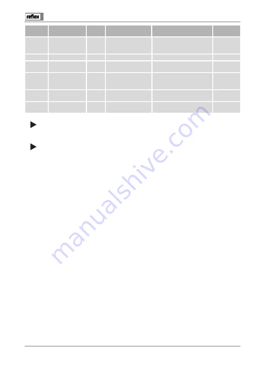
ER Code
Alarm
Floating
contact
Causes
Remedy
Alarm reset
31
EEPROM defective
–
•
EEPROM defective
•
Internal calculation
error
Inform Reflex Customer Service.
"OK"
32
Undervoltage
–
Supply voltage too low.
Check power supply.
–
33
Adjustment
parameter faulty
–
EPROM parameter memory
defective.
Inform Reflex Customer Service.
–
34
Main board
communication faulty
–
•
Connecting cable
defective.
•
Main board defective.
Inform Reflex Customer Service.
–
35
Digital input voltage
faulty
–
Short-circuit of input
voltage.
Check the wiring at the digital
inputs (water meter, for example).
–
36
Analogue input
voltage faulty
–
Short-circuit of input
voltage.
Check the wiring at the analogue
inputs (pressure/level).
–
Note!
Messages identified with "OK" must be confirmed with the "OK" button on the display. The device operation is otherwise
interrupted. The readiness for operation is maintained for all other messages. They are displayed.
Note!
If necessary, you can set the output of messages via a floating contact in the Customer menu.


