19
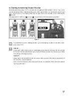
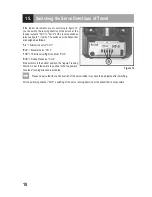
16. Changing the Control Lever Allocation
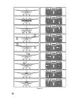
If you want to control your flight model according to the chart shown in figure 10 (mode II), you can skip this section.
If you prefer the throttle function on the right control lever and the elevator function on the left one (mode I), you may
convert the transmitter accordingly.
To make the necessary changes, some experience with remote control transmitters is required. Therefore you should
consult an experienced model maker or a model construction club if you do not feel capable of undertaking the pro-
cedures described in the following.
• Remove the transmitter batteries.
• Unscrew the four screws by means of a Phillips-tip screwdriver from the rear panel of the transmitter and lift the rear
panel carefully.
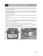
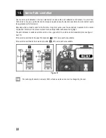
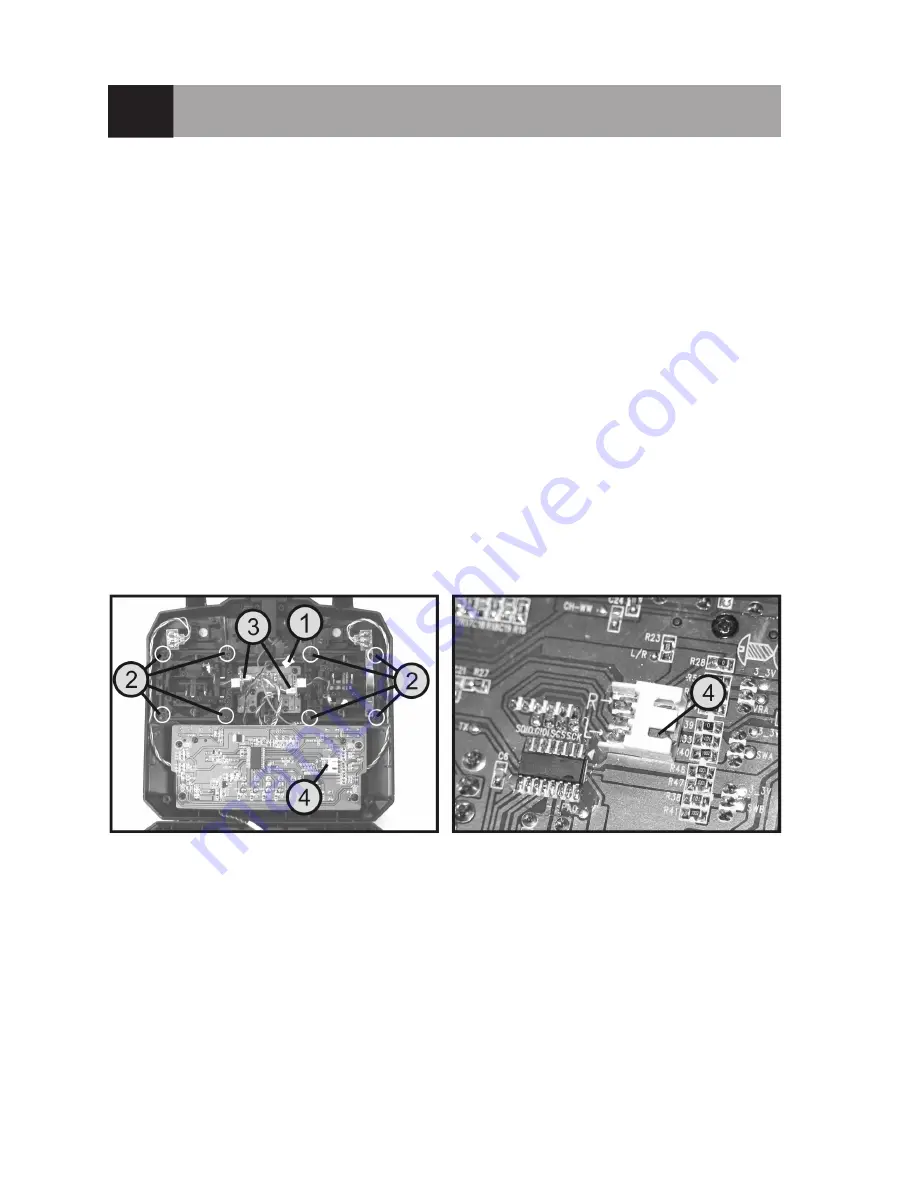
• After you have disconnected the plug connector of the student socket (1), you can fold the rear of the transmitter
down.
• For this, loosen the four screws at the control lever units (2) and swap the two units. You need to turn both control
lever units by 180° so that the connections of the control lever potentiometers (3) are aligned to the inside again.
• Then screw on the control lever units again.
• Use pointed pliers or pincers to pull the jumper (4) from the position "L" and reinsert it in position "R".
• Then close the connection plug of the student socket (1) again and place the rear panel on the transmitter housing.
Observe that no lines are caught between the housing halves.
• Tighten the four attachment screws of the rear wall again and check for correct function of the remote control.
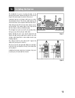
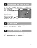
Figure 13
Summary of Contents for HT-5
Page 1: ...Operating instructions Remote Control HT 5 2 4 GHz Item No 1414497 Version 04 16 ...
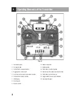
Page 16: ...16 Figure 10 ...
Page 21: ...21 Figure 14 ...
Page 29: ...29 ...
Page 30: ...30 ...
Page 31: ...31 ...

