14
13. Setting the Trim
The trim mostly serves to correct the slight inclination of the servo levers due to the interlock and the connected ir-
regular control movements. Additionally, there is the option to adjust the model in operation precisely, e.g. if it is not
flying straight although the control lever is in the middle position.
Then the linkage or rudder rods must be adjusted so that the trim has its original value (90°-range between servo lever
and rods) again and the model still runs straight.
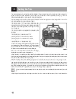
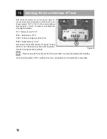
The remote control "HT-5" has a finely tuned digital trim
-
ming with which the first four control channels can be indi
-
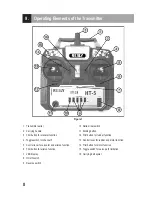
vidually set with a trimming button (also see figure 1, items
3, 6, 12 and 14).
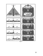
The trimming buttons are assigned the following control
functions:
Trimming button 3 = elevator servo "CH2"
Trimming button 6 = aileron/roll servo "CH1"
Trimming button 12 = rudder/tail servo "CH4"
Trimming button 14 = throttle servo "CH3"
To check the setting of the digital trimming, first switch on
the transmitter and then the receiver. If a trimming button
is moved to the side or up or down and held, the transmit-
ter will emit brief signal sounds in a quick sequence.
The servo of the respective control channel will change
the position of the servo lever in small steps.
When the end of the trimming range is reached, the signal sounds go out and the servo lever stops turning. If the
trimming button is then deflected in the opposite direction and held, the signal sounds sound again and the servo lever
turns back to the middle position step by step.
When the middle position of the trimming range has been reached, the remote control issues a longer signal sound.
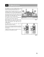
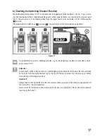
Now set the middle positioning of the trimming in all four channels and install the servo levers so that they are at a
90° angle to the rods. Since the servo levers and the servo axis are interlocked, very small inclinations of the servo
lever cannot always be avoided. In this case, the trimming of the respective channel must be adjusted slightly from the
middle to return to the 90° angle of the servo lever to the linkage rod (see figure 8).
The set trim value is automatically saved in the remote control and is retained even after switching it off and
on.
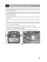
When using the electrical model with a flight controller, the trim for channel 3 also needs to be set to the middle value.
Figure 9
Summary of Contents for HT-5
Page 1: ...Operating instructions Remote Control HT 5 2 4 GHz Item No 1414497 Version 04 16 ...
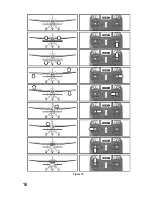
Page 16: ...16 Figure 10 ...
Page 21: ...21 Figure 14 ...
Page 29: ...29 ...
Page 30: ...30 ...
Page 31: ...31 ...

