15
14. Checking the Servo Directions of Travel
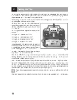
a) Checking the Control Lever Functions
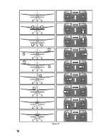
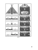
For figure 10 for this section, see the next page.
Connect the servos inserted in the model to the receiver. Pay attention to the assignment of the receiver outputs as
described above.
If your model has two aileron servos, there is the possibility of operating both servos with a V-cable at the
receiver output "CH1".
Take the transmitter into operation, then the receiver. If attached correctly, the servos at outputs 1, 2, 3 and 4, or a
speed controller at output 3, should react in the right direction to the movements of the control levers according to the
illustrations in figure 10.
The linkage rods of the rudders must be adjusted so that the rudders are all aligned precisely centrally if the control
lever and the trimming are in the central position (also see top sketch in figure 10).
The left control lever for motor control can be pushed forward and back without being moved back to the
middle position by spring force. It always remains in the position into which it was last moved.
Using a throttle servo:
If the model is operated with a combustion engine, the throttle servo rods must be adjusted so that the motor runs idle
when the carburettor is nearly closed when the left control lever is in the bottom position. Only when the trim for the
motor function is also pushed all the way to the bottom, the carburettor must close completely so that the combustion
engine is switched off.
If the control lever is pushed to the top-most position, the throttle in the carburettor must be completely opened so that
the motor can run at full power.
Using an electrical motor with flight controller/speed controller:
An electronic flight controller/speed controller connected at the receiver output "CH3" must be set so that an electric
motor is off when the left control lever is in the bottom position. For electrical models, the flight controllers/speed
controllers often offer the option to teach in the respective control lever positions for "motor off" and "maximum perfor-
mance". Further information on this can be found in the operating instructions of the flight controller/speed controller.
Attention!
Only perform the motor test in an electric model when the model is reliably secured against rolling away.
Make sure that neither objects nor body parts are in the rotating and suction areas of the propeller during
the motor test.
If the servos or rudders react in precisely the opposite manner as shown in figure 10, the reverse switches (see fol
-
lowing chapter) can swap the running direction of the respective servo.
Summary of Contents for HT-5
Page 1: ...Operating instructions Remote Control HT 5 2 4 GHz Item No 1414497 Version 04 16 ...
Page 16: ...16 Figure 10 ...
Page 21: ...21 Figure 14 ...
Page 29: ...29 ...
Page 30: ...30 ...
Page 31: ...31 ...

