Motion
Scope
â
PCI High Speed Video System
1. The signal input is held at +5 volts. A contact closure to ground caused by the Trigger pulls
the input to 0 volts to stop recording. This presents a falling signal edge to the trigger input
so you must check the Falling box in the Trigger dialog box.
2. A contact closure holds the input to 0 volts. The trigger opens the contacts causing the input
to rise to +5 volts. This presents a rising signal edge to the trigger input so you must check
the Rising box in the Trigger dialog box.
3. A TTL- or CMOS-compatible logic signal, or other ground-based logic with a maximum of 2K
ohms holds the Trigger input at 0 volts. The Trigger signal allows the Trigger input to go to
+5 volts to stop recording. This signal can go as high as +30 volts. You must check the
Rising box in the Trigger dialog box.
2.8.5 The Phase-Lock Input and Output
1. Determine which system will be a master and generate the sync pulses, or a slave and
receive the sync pulse from a master (see Figure 1-6).
2. At the master system, connect a BNC connector and cable from the PHASE LOCK OUT
connector.
3. Select the Settings menu for the Master unit. In the Master/Slave line, select Master.
4.
Series Connection.
Connect the cable from Step 2 to the PHASE LOCK IN connector on the
first slave unit. In any downstream
Motion
Scope system, connect a BNC connector and
cable from the PHASE LOCK OUT from the first slave to the PHASE LOCK IN of the next
slave unit.
5.
Parallel Connection.
Install a tee to the cable installed in Step 2. Connect the tee to the
Phase Lock IN connector of the Slave, and install cables and tees to the downstream Slaves.
6. Select Slave in the Master/Slave line of the Settings menu on all Slave units.
2.8.5.1 Connecting
Motion
Scope Systems to an Equipment Source
One or more systems can be synchronized to an equipment source. If there is more than one
Slave unit, the connections can be series or parallel. Follow the instructions given in 2.8.5 above,
substituting the equipment source for the Master unit.
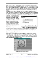
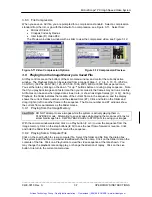
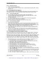
The Phase Lock signal from the equipment source must conform to the following specification.
The normal signal level is +5 volts, which must fall to 0 volts prior to the next frame exposure.
This signal’s rising edge coincides with the start of a frame exposure (see Figure 2-4).
Figure 2-4 The Phase Lock Signal and Circuit.
_____________________________________________________________________________
9400-0010 Rev. S
2-5
OPERATOR'S INSTRUCTIONS
Artisan Technology Group - Quality Instrumentation ... Guaranteed | (888) 88-SOURCE | www.artisantg.com


