Motion
Scope
â
PCI High Speed Video System
2.5 Power On and Loading the Software (Windows NT 4.0)
1. Turn the computer ON.
2. Insert
the
Motion
Scope PCI CD-ROM into the drive. Follow the installation directions.
3. When installation is complete, restart the computer.
4. Click on Start/Programs, highlight and click on
Motion
Scope. Monitor shows the Initial menu.
2.6 Viewing the Live Picture
·
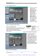
Click on
Open – Camera 1
. This opens the Camera 1 window showing the live view from the
camera. If the Camera responds, go to paragraph 2.5 for the external connections, or to
Section 4 for operating instructions.
·
If there is no picture, adjust the aperture ring. If there is still no picture, increase the light on
the subject.
·
If the image is not clear adjust the focus of the lens. If a simple lens adjustment does not
focus the picture, adjust the back focus by loosening the screw under the lens mount using a
3/32 Allen key. Rotate the lens mount to focus the picture. Tighten the screw.
Warning!
Do not over-tighten this screw or you will damage the locking ring and lens thread.
·
If the system does not respond, refer to Section 6, Maintenance and Troubleshooting.
2.7 Setting the Camera Options
This procedure gives the camera a reference or name, and determines whether the default
camera size and position is loaded each time, or whether any changes are stored when you exit
the program.
2.7.1 Naming the Camera and Loading Default or New Data
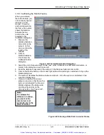
1. Click on the Setup… button. This brings up the Properties dialog box, General tab.
2. Enter a name for the Camera 1. This name will appear on the title bar of the Camera 1
window.
3. Check Save Camera Size and Position if you wish to store the size changes you may make.
4. Click
OK.
2.8 Connecting the External Options
This section gives details of the connections and electrical specifications for the Trigger, Strobe,
Data Recording, Video Out and Phase Lock options. Connect the input or output to the
appropriate BNC connector attached to the camera cable. The switch setting instructions refer to
the DIP switches on the adapter rear plate above the camera cable connector.
2.8.1 Composite Out
The “COMPOSITE OUT” BNC connector supplies a video signal to an external monitor, VCR or
computer. A computer must have a video capture board to receive or transmit video to the
Control/Display Unit. The system is factory set to the NTSC (30 fps) or PAL (25) standard.
Change this standard by resetting Switch 8.
2.8.2 The Strobe Output
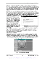
The Strobe signal is a positive-going pulse that rises when the shutter opens and falls when the
shutter closes (see Figure 2-2). The Strobe signal is always enabled. The length of the pulse
depends on the record
rate set (frames per
second) and the shutter
setting (1X - 20X, where
X is the record rate).
Refer to Appendix C.
Figure 2-1 The Strobe Circuits.
_____________________________________________________________________________
9400-0010 Rev. S
2-3
OPERATOR'S INSTRUCTIONS
Artisan Technology Group - Quality Instrumentation ... Guaranteed | (888) 88-SOURCE | www.artisantg.com


