955-0002_v3.3, Rev-B
COPYRIGHT © 2012 RED.cm, Inc.
237
237
BACK FOCUS ADJUSTMENT
WARNING: THERE IS A SCREW-IN METAL PLUG INSTALLED IN THE CAMERA BODY COVERING
THE BACK FOCUS SCREW. THIS PLUG MUST BE REMOVED BEFORE PERFORMING A BACK
FOCUS ADJUSTMENT. TO REMOVE THE PLUG, USE A T-10 TORX SCREWDRIVER.
NOTE: To perform this procedure as written, you must have a PL mount and RED Focus™.
Back focus is adjusted by turning the back focus adjustment on the top of the camera’s front plate using
a T-10 Torx screwdriver. This screw is indicated by a
Siemens Star
with an arrow pointing to its location.
Back Focus Adjustment Location
1.
Remove the screw-in plug located in the back focus adjustment opening using a T-10 Torx
screwdriver.
2.
Place the camera on a level, stable surface or mount the camera on a tripod.
3.
Install RED Focus to the camera PL mount.
a.
Remove the camera lens or sensor cover if equipped.
b.
Install RED Focus onto the camera in the position shown.
c.
Ensure RED Focus is secured to the camera with the camera lock ring.
RED Focus Properly Installed on Camera
Summary of Contents for EPIC-M
Page 1: ......
Page 244: ...955 0002_v3 3 Rev B COPYRIGHT 2012 RED cm Inc 243 243 Side View ...
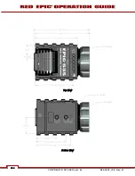
Page 245: ...COPYRIGHT 2012 RED com Inc 955 0002_v3 3 Rev B 244 244 244 244 Top View Bottom View ...
Page 246: ...955 0002_v3 3 Rev B COPYRIGHT 2012 RED cm Inc 245 245 Back View ...
Page 247: ...COPYRIGHT 2012 RED com Inc 955 0002_v3 3 Rev B 246 246 246 246 APPENDIX M RESOLUTION CHART ...
Page 248: ...955 0002_v3 3 Rev B COPYRIGHT 2012 RED cm Inc 247 247 APPENDIX N MENU MAPS ...


