24
8. Maintenance
- cont.
Belt Tension
After the first 5 hours of operation check belt
the tension.
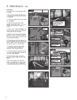
1. Remove the cutter guard assembly from the
side of the machine by removing the 4 phillips
screws
Fig.8.8
.
2. Undo the cap head bolt and remove the drive
belt cover
Fig.8.9
.
3. Check tension by pushing against belt
Fig.8.10
. play should be approx. 15 – 20 mm.
If required, the belt tension is adjusted as
follows:
4. Slacken the four cap head bolts
Fig.8.11
. this
enables the motor position to be moved which
is how the belt tension is adjusted.
5. To reduce tension; squeeze the belt together
Fig.8.12
. this raises the motor and reduces the
belt tension. Tighten the bottom two cap head
screws to secure the setting.
6. To increase tension; lever the motor housing
downwards
Fig.8.13
. this lowers the motor and
increases the belt tension. Tighten the bottom
two cap head screws to secure the setting.
7. Once correct tension has been achieved,
re-assemble the side of the machine. First
replace the switch and drive belt cover.
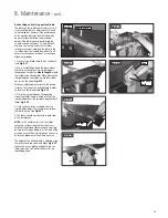
8. Offer the cutter guard into position ensuring
the handle is pointing downwards and the end
teeth mesh together.
Fig.8.14
.
9. Move the handle upwards so the cutter
guard is lowered and touches the planer table.
Fig.8.15
.
10. Re-attach the cover plate with the four
phillips screws,
Fig.8.16
. To set the movement
of the cutter guard mechanism tighten each
screw fully then loosen each one off half a turn.
Fig.8.8
Fig.8.10
Fig.8.9
Cap head bolt
Drive belt
cover
Fig.8.12
Fig8.11
2 x lower cap head bolts
Fig.8.13
Lever motor housing
downwards; here the
end of a spanner is
being used
Fig.8.14
End teeth meshing
together
Handle pointing
downwards
Locate bar in top
of drive belt cover
Fig.8.15
Handle pointing
upwards
Cutter guard
touching the table
Fig.8.16
Summary of Contents for PT260
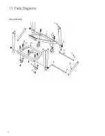
Page 28: ...28 11 Parts Diagrams Stand Wheel Kit ...
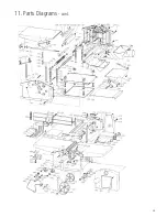
Page 29: ...29 11 Parts Diagrams cont ...
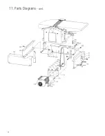
Page 30: ...30 11 Parts Diagrams cont ...
Page 34: ...34 ...
Page 35: ...35 ...


