13
Fig.4.5
Depth Scale
4. Machine Assembly
4.1 Fixing the in-feed table
1. Remove the four socket head cap screws from
table cover rails already fitted and remove the
cover rails
Fig.4.1
.
2. Take the in-feed depth of cut adjustment
bar and remove the collar and sprung washer
Fig.4.2
.
3. Thread the bar through underside of table
then re-fit and secure collar
Fig.4.3
.
4. Offer the table up to the machine whilst
threading the depth of cut adjustment bar into
the spacer shaft
Fig.4.4.
5. Fit the infeed table into position and wind the
depth of cut bar until the uppermost line on the
depth scale is registered with the line on the
side of the table
Fig.4.5
. Re-fit and secure the
table cover rails,
Fig.4.6.
these rails should not
be fully tightened as the table needs to slide up
and down in order to adjust the depth of cut. As
a guide fully tighten the socket head cap screws
then unscrew by 1/4 turn.
4.2 Fixing the thicknessing dust
extraction outlet
Moving round to the opposite side of the
machine, locate the slotted extrusion and place
the extraction outlet into position
Fig.4.7
.
Secure this outlet into slot using 4 self tapping
screws and washers
Fig.4.8
4.3 Fixing the outfeed table
1. Place the outfeed table over the lugs on the
planer body and lock the table in place with the
levers.
Fig.4.9.
4.4 Table adjustment
Table adjustment is not necessary at this
stage. See the table adjustment part of the
maintenance section.
Fig.4.1
Fig.4.2
SOCKET HEAD
CAP SCREW
TABLE COVER
RAILS
COLLAR
Fig.4.3
COLLAR & SPRUNG
WASHER
Fig.4.4
SPACING SHAFT
Fig.4.6
SOCKET HEAD CAP SCREW
TABLE COVER
RAIL
DEPTH OF
CUT BAR
DEPTH SCALE
Fig.4.7
Fig.4.8
Slotted
extrusion
Slot
Self tap screw
& washer
Fig.4.9
Locating
Lugs
Locking
levers
SPRUNG WASHER
Summary of Contents for PT260
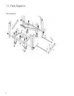
Page 28: ...28 11 Parts Diagrams Stand Wheel Kit ...
Page 29: ...29 11 Parts Diagrams cont ...
Page 30: ...30 11 Parts Diagrams cont ...
Page 34: ...34 ...
Page 35: ...35 ...


