19
6. Operation & Planer Thicknesser Practice
- cont.
6.4 Planing
Fix the extraction port in position as shown in
Section
6.1
.
This operation is carried out for straightening
a workpiece and for trimming the long side of
panels. Place workpiece flush on to in-feed table,
with your left hand set the cutter guard to the
required height (workpiece should be run clear
of the guard). Start the machine and push timber
slowly and steadily against the cutterblock,
moving hands over the cutter guard as the
timber is pushed under it, see
Fig.6.5A
.
The depth of cut can be altered by setting the
infeed table to line up with the marking on the
scale. The top line is zero and the bottom line is
a 3 mm cut. It is not advised to take the deepest
cut, a shallow cut will give better results and put
less strain on the machine
Fig.6.5B
.
To increase the depth of cut simply rotate the
infeed adjustment knob anti clockwise
Fig.6.5C
.
6.5 Jointing
For planing the narrow sides of a workpiece,
release the cutter guard's lock lever and set the
cutter guard to the width of the workpiece. The
spring on the end of the cutter guard should
exert a slight pressure against the workpiece.
Lock blade guard in place and start the machine.
Push workpiece slowly and steadily against
cutter block. Ensure that fence is set at the
required angle and the workpiece is kept flush
against the fence
Fig.6.6
.
This gives you 2 datum surfaces; explanation
below
Fig.6.7A
.
After straightening
side 1
, turn the workpiece
90º so that
side 1
now lines up along the fence.
Surface
side 2
at 90° in order to carry out
thicknessing: this way it is possible to obtain a
finished piece planed on all 4 sides.
When
side 1
is positioned flat against the
thicknessing bed,
side 3
is cut exactly square
Fig.6.7B
. Likewise when
side 2
is positioned
flat against the thicknessing bed,
side 4
is cut
square the end result is a completely square
piece of timber
Fig.6.7C
.
Before proceeding with thicknessing, carefully
read the advice on safety and planer-protection
adjustment on the following pages.
Fig.6.5A
Fig.6.6
Fig.6.5B
Depth Scale
Fig.6.5C
Adjustment Knob
90º
Fig.6.7A
Thicknessing
bed
1
3
2
Fig.6.7B
Cutterblock
Thicknessing
bed
2
1
4
3
Fig.6.7C
Side 1
Fence
Surface
planing table
Surface
planing table
Side 1
Side 2
Side 1
Side 3
Side 2
Side 4
Side 1
Side 3
Side 4
Side 2
Plastic spring
Summary of Contents for PT260
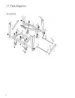
Page 28: ...28 11 Parts Diagrams Stand Wheel Kit ...
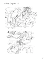
Page 29: ...29 11 Parts Diagrams cont ...
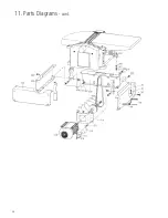
Page 30: ...30 11 Parts Diagrams cont ...
Page 34: ...34 ...
Page 35: ...35 ...


