


30
Warning: Ensure that the power supply to the lathe is turned
off and disconnected before starting the conversion of your
existing lathe.
1. Check items supplied against
Fig 15.1
shown before proceeding with
conversion of the lathe.
2. Clear unnecessary items from the area of your lathe to ensure that no
parts are lost during the change over.
3. Unlock headstock clamp and slide the assembly towards the tailstock end
of the bed tubes,
Fig 15.2
.
4. Release M12 nut and washer securing end bracket,
Fig 15.3
.
NOTE: If the lathe is mounted on the DML24S Legstand, the legs
must also be removed and refitted to new end bracket.
5. Now Re-attach the DML24S Legstand (if used) to the replacement end
bracket,
Fig 15.4
.
6. Refit bed rails and secure using M12 Nut. Threaded bar and washer,
Fig 15.5
.
7. Check bed rails for alignment as outlined in
section 6
before proceeding.
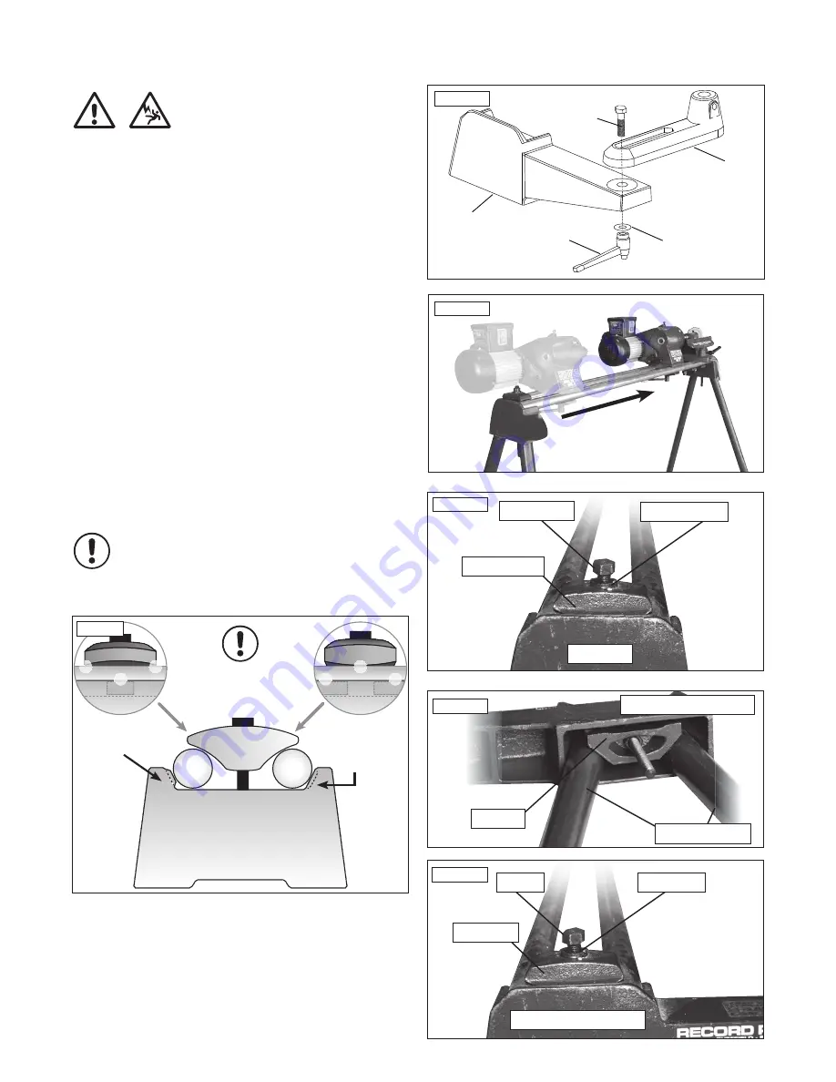
8. Secure Bowl Rest Banjo to End Bracket using M12 x 50mm Bolt, Washer
and M12 Ratchet Handle.
9. Adjust banjo/toolrest to suit your workpiece. Your bowl rest is now ready
for use.
14. DML-BR Bowl Turning Attachment Assembly
Bowl Rest
Banjo
Part No.
(CKBJ)
M12 x 50mm Bolt
Part No. (AUXB)
M12 Washer
Part No. (ZABO)
M12 Ratchet
Handle
Part No. (CKRH)
End Bracket
Part No.
(CKER)
Fig.15.1
Move Headstock
Fig.15.2
M12 Nut
M12 Washer
Angle Strap
End Bracket
Fig.15.3
M12 Nut
M12 Washer
Angle Strap
Replacement End Bracket
Fig.15.5
i
Kg
i
Kg
Please note: When re-assembling the lathe, ensure the kinematic
points are assembled in the correct configuration. See Fig 15.6.
i
Kg
Fig.15.6
Central single
raised pad
Central recess
creates two
pads
Kinematic principle
in use - 3 points of
contact created
i
Kg
Replacement End Bracket
Wedge
DML24S Legstand
Fig.15.4


