


14
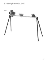
6. Assembly Instructions - cont.
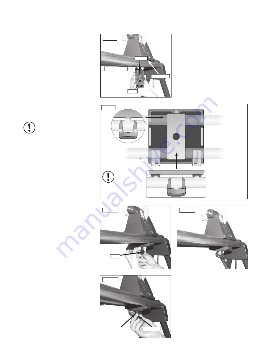
Fig.6.6B
Tailstock from
below
Tailstock
from rear
Tailstock
from front
Kinematic principle
in use - 3 points of
contact created
i
Kg
Attaching the Tailstock
1. Place the tailstock onto the bed bars at the
right hand end of the assembly, again noting
that the raised area for the kinematic design is
at the front of the lathe,
Figs.6.8A
&
6.8B
.
2. Introduce the square strap underneath the
bed bars, ensuring that the recess is to the front
of the lathe opposing the raised area on the
tailstock,
Figs.6.8A
&
6.8B
.
3. Place the bush onto the tailstock screw,
Fig.6.9
.
4. Feed the washer onto the tailstock screw
under the bush and tighten the nyloc nut to
secure the assembly,
Fig.6.10
.
5. Use a spanner to tighten the Nyloc nut on the
underside of the tailstock assembly,
Fig.6.11
.
Please note: Sensitivity of the cam is
adjusted with this nut. To reduce travel
on the cam and increase clamping force,
tighten the nut. To increase travel on
the cam and reduce the clamping force,
slacken the nut.
Fig.6.9
Bush
Fig.6.11
Fig.6.10
Washer
Nyloc nut
Fig.6.8
Raised area
Recess
2 pads
Tailstock screw
i
Kg


