


11
Before assembling and using your lathe, you must have a sturdy bench or stand for it. We recommend the Record Power DML24S Legstand. If you wish to
build your own bench, remember that the lathe is heavy. The bench must not move during use.
GENERAL NOTES
1. The first decision to be made when installing a lathe is the selection of the ideal location. For best results the location should have a solid floor of
concrete or similar. Wooden floors will always have a certain amount of natural movement that will amplify any vibration present whilst turning. This is
particularly noticeable if the machine is installed in a garden shed as the quality of materials used to construct the floor are generally not as good a quality
as those used in the building industry. If the garden shed or workshop is the only option available, then the floor should be strengthened or reinforced to
increase rigidity and dampen vibration.
2. The second, and possibly the most important decision is the selection of an appropriate bench or stand on which to mount the lathe. If using a wooden
bench, whether it is an existing bench or purpose built, there are several points that should be kept in mind:
• The bench top should have a minimum thickness of 2" (50mm) and additional braces should be fitted length ways along the underside of the bench to
improve rigidity.
• The legs should be of a suitable type and cross section to support the bench. This will of course depend on the overall size of the bench and type of lathe.
The minimum cross section of wooden legs should be approximately 4" (100mm).
• The top of the legs should be located on the underside of the bench at approximately the same distance apart as the end brackets of the lathe. If the legs
are mounted too close together the bench will become unstable. If the legs are too far apart the bench may have a tendency to sag under the weight of
the lathe.
• The legs should NEVER be truly vertical, and should always slightly splayed by 5 degrees across the length and width of the bench. This will not only
increase stability but also reduce vibration. Vertical legs will act like a trampoline, so that any force exerted downwards will simply rebound from the floor
back up the legs and into the bench.
• The legs should be braced at approximately one third of their height from the floor, and should be braced both along the length and width of the bench.
• If possible the bench should be bolted to the floor, but it should NEVER be fixed to any of the surrounding walls and should ALWAYS be free standing.
6. Assembly Instructions - cont.
WARNING
Inadequate strength of the bench could result in failure of the bench, which could cause the lathe to fall. Serious injury could occur. The lathe
must not shift or move. If there is movement when not running, this movement will be exaggerated when in use. Serious injury could occur and
work quality will suffer. To reduce movement, bolt the bench to the floor and the lathe to the bench.
CAUTION
To avoid back injury, get help lifting the lathe. Bend your knees, lift with your legs, not your back. The headstock and bed bars in particular are
very heavy.
i
Kg
i
Kg
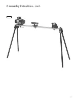
Assembly of the Bed with the Optional
Leg Stand
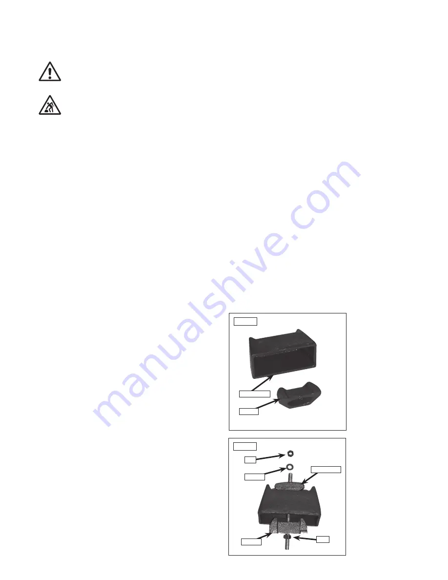
1. To assemble the bed bars and optional legstand take one of the end
brackets and wedge,
Fig.6.1
(supplied with optional DML24S).
2. Unscrew the nut and washer from one end of a long bolt and feed the
long bolt through the holes in the wedge, end bracket and angle strap.
Ensure that the wedge is the correct way around in relation to the end
bracket,
Fig.6.2
.
3. With the end bracket laid on the floor, feed two of the stand legs up into
the end bracket as shown
Fig.6.3
. Replace the washer and nut, but do not
tighten at this stage.
Ensure that the kinematic points on the angle strap oppose this on the end
bracket
Fig.6.4A
.
4. Locate the bed bars in position under the angle straps and tighten in
position
Fig.6.4B
.
Assemble the second set of legs with the remaining end bracket, angle
strap and wedge as instructed above.
Please note: If the optional DML-BR bowl bracket is to be fitted
use this in the assembly procedure at this point in place of the
second end bracket.
5. Lay the second set of legs on the floor. Hold the already assembled end
of the bed bars/legstand above the legs on the floor and lower them into
position
Fig.6.5
.
The end of the bed bars/legstand which is aloft must now be supported
whilst the end resting on the floor is tightened. It may be advisable to seek
assistance for this
Fig.6.6A
.
Fig.6.1
Wedge
End Bracket
Fig.6.2
Nut
Washer
Angle strap
Nut
Wedge


