


16
6. Assembly Instructions - cont.
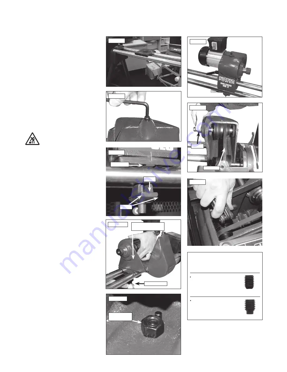
TIP
The pulleys lock onto the shafts using two
grub screws.
A knurled base grub screw
which locates into the
dog grub screw.
Then the dog grub screw
locates into the groove
on the shaft.
Fig.6.18
Single pad
2 pads
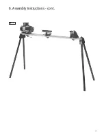
Headstock Assembly
1. Place the saddle on the bed bars,
Fig.6.16
.
1. Remove the cover plate from the headstock
using the Allen key,
Fig.6.17
.
2. When fitting the remaining locking handle
and square strap ensure that recess part of
the square strap is on the same side as the
white indication line on the saddle,
Fig.6.18
.
Carefully lower the headstock onto the saddle,
it is advisable to angle the headstock assembly
so the motor rests on the bed bars, this will bear
most of the weight,
Fig.6.19
.
3. Now feed the locking handle through the
saddle and headstock, fasten the hex nut
on to the locking handle which is showing
inside the headstock,
Fig.6.19
. Ensure the nut
seats against the roll pin on the inside of the
headstock,
Fig.6.20
.
Caution: This component is very heavy
and will not be stable on the bed bars
until the nut and bolt are fastened.
Assistance should be sought.
4. Tighten the locking bar into the nut securing
the headstock assembly,
Fig.6.21
.
5. Rotate the spindle by hand and inspect the
drive belt on the pulleys ensuring that it runs
true, Fig.
6.22
. If it doesn’t, remove the first
grub screw (these are two grub screws in the
same hole. A knurled grub screw on top and a
dog grub screw underneath which rotate on a
keyway on the spindle), loosen the dog grub
screw and slide the stepped pulley along the
motor shaft until the correct position is achieved
and the belt is aligned straight.
6. Now tighten the dog grub into the groove
on the motor shaft. Then take the second grub
screw and tighten this in on top of the dog grub
screw locking the position of the motor pulley,
Fig.6.23
.
7. Finally replace the headstock cover plate and
secure this with the Allen bolt.
The assembly of the lathe is now complete,
Fig.6.24
.
Fig.6.17
Fig.6.19
Fig.6.23
Fig.6.22
Drive belt
Spindle
Fig.6.20
Nut up against
roll pin.
Fig.6.16
Locking handle nut
inside headstock base
Locking handle
Fig.6.21
Recess
i
Kg


