Real Flame Element 1200 MARK 2 Installation And Operation Manual Download Page 52

52

Page

FLUE TERMINATION LOCATIONS 

This section is used to determine where your Balanced 
Flue termination will be located.
Flue terminations shall not be recessed in walls or sidings. 

EXTREMELY IMPORTANT

•  In heavy snow areas take extra care to prevent 

blocking flue termination with snow removal 
equipment.

•  Flue gases exiting flue terminals are very hot and must 

not be restricted to assure fireplace combustion is not 

affected.

•  Do not place, build any obstruction, plant any 

bushes or for any reason attempt to conceal the flue 
termination. To do so will affect the operation of the 
fireplace and may be hazardous.

•  This unit must always vent directly to outdoors.

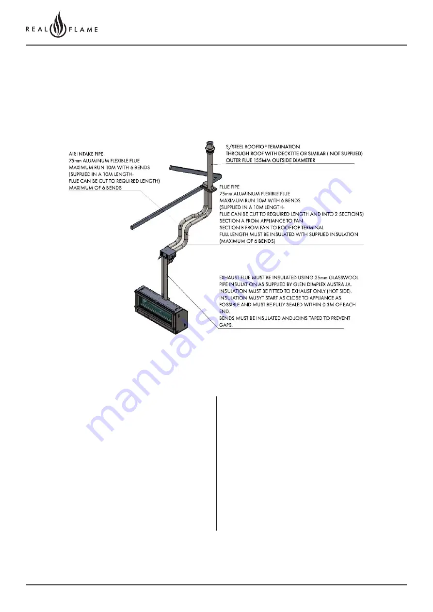
Flue runs 5m to 10m length roof top termination only 

Vertical roof termination (S/Steel rooftop termination)

Summary of Contents for Element 1200 MARK 2

Page 1: ... this manual before installing and operating this appliance Failure to follow these instructions may result in a possible fire hazard and or injury and will void the warranty The Real Flame Element space heater is suitable to be installed into a frame out installation Designed to operate on Natural gas LPG and ULPG Approval no GMK 10441 SCAN FOR THE L ATEST VERSION ...

Page 2: ...NAL MOTOR 46 5 10M INSUL ATED FLUE CONFIGURATION INSTALLATION INSTRUCTIONS 50 EXTERNAL WALL MOUNTED FAN MODULE INSTALLATION 54 INTERNAL FAN AND WALL TERMINATION INSTALLATION 58 INTERNAL FAN AND ROOF TERMINATION 68 ROOFTOP TERMINATION WITH EXTERNAL MOTOR 73 10 13 5M POLYPROPYLENE FLUE CONFIGURATION INSTALLATION INSTRUCTIONS 78 SETUP WITH EXTERNAL WALL MOUNTED FAN TERMINAL 82 INTERNAL FAN AND WALL T...

Page 3: ...occur inside the firebox This is a normal condition and is not covered by warranty WARNING The Element space heater has a primary safety glass fitted in front of the glass door This safety glass is fitted to this appliance to reduce the risk of injury from burns and at no time should this glass be permanently removed For protection of young children or the infirm a secondary guard is required The ...

Page 4: ...High 25 Low Operating Pressure TPP 0 85kPa High 0 55kPa L ow 2 50kPa High 1 70kPa L ow 2 55kPa High 1 70kPa L ow Max Min Inlet Pressure Range 1 13kPa 5 00kPa 2 75kPa 5 00kPa 2 75kPa 5 00kPa Injector Size 3 X 2 25mm 3 X 0 95mm 3 X 0 90mm Aeration Settings Media Setup Natural Gas LPG ULPG Driftwood 5 0 10 0 Not Available Coals and Logs 5 0 10 0 Full open Pebbles 5 0 10 0 Full open Redgum and Coals 5...

Page 5: ...0 kPa Low 2 50kPa High 1 70 kPa Low Max Min Inlet Pressure Range 1 13kPa 5 00kPa 2 75kPa 5 00kPa 2 75kPa 5 00kPa Injector Size 3 X 2 30mm 3 X 1 05 3 X 0 95mm Aeration Settings Media Setup Natural Gas LPG ULPG Driftwood 4 5 4 5 2 0mm RH end 10 10 10 Not Available Coals and Logs 4 5 4 5 2 0mm RH end 10 10 10 Full open Full open Full Open Pebbles 4 5 4 5 2 0mm RH end 10 10 10 Full open Full open Full...

Page 6: ...6 Page OPERATION INSTRUCTIONS ...

Page 7: ...wait 5 minutes before reattempting to light the fire NOTE The Element MK2 is fitted with a gas pressure switch in the event of no gas gas supply turned off or low gas pressure the appliance will not operate REMOTE CONTROL GUIDE The Element MK2 heater is controlled completely by the use of the remote control this remote can be used either as a manual operation or an auto operation The remote thermo...

Page 8: ...o that period s setting Programming Each day of the week can be programmed individually for 4 periods P1 P2 P3 and P4 making a total of 28 programmed periods Alternatively a weekday program can be set so the same program is used for Monday Friday Similarly a weekend program can be set for Saturday Sunday The entire week can also have the same program Alternatively a weekday or weekend program can ...

Page 9: ... RF Thermostat to the Control Unit causing the Control Unit to learn its ID WARNING When the RF thermostat is in the Auto mode and the room temperature drops below the minimum temperature the fire and fan will come on and operate until the room temperature is 3 above the minimum and then turn off therefore The minimum temperature should be set at a temperature that is not likely to cause the fire ...

Page 10: ...ing valve has been installed into a fireplace with the WiFi module connected WiFi Set up From Factory settings the Fireplace will broadcast an Access Point for the Mobile App to join with the Access point names have the following format Realflame_XXXXXX Where XXXXXX is the last six digits of the WiFi modules MAC addresses the Access point is secured with the default password realflame Joining the ...

Page 11: ... example the RealFlame_36AAAA is the fireplace to select Step 6 Once you select the network of your fireplace you will be transported to a screen to input the network password The password will be realflame Step 4 When this screen pops up please switch your fireplace off for 10 seconds and switch on again from the isolation switch and click on Minimise App If it s already off switch on the firepla...

Page 12: ...ans you have connected to the device using the fireplace WiFi Check Step 1 1 under Setting up remote access to the fireplace to connect to your fireplace from any location Step 9 Congrats you have connected to the fireplace Sit back relax and increase or decrease the temperature as you please Step 10 In case you want to change the name of your fireplace connection click on the settings button on t...

Page 13: ... this tab opens Step 13 Select your home WiFi network and input the password This process links the fire to your WiFi Make sure your phone is connected to the same network the fire is Setting up remote access to the fireplace eg Using the phone or tablet remotely to activate the fire when not at residence Note gas fireplace requires connection to home WiFi network ...

Page 14: ... WiFi connection to home WiFi network on Open Realflame fire app Click YES Step 15 Clicking Yes will open the registration section which once completed will allow you to access your fireplace from anywhere Put in the details of your preferred username and preferred password eg John Smith p w delta22 check the save details tab and click ok Record the username and password for future reference Step ...

Page 15: ...ireplace is powered off at the Main switch upon being powered on the Fireplace will show its Access point Realflame_XXXXXX for 30 seconds If you join the access point with your mobile device you will be able to change the network the Fireplace is currently connected with via the mobile App If you do not join the Access point the Fireplace will join the network that is has settings saved for or if ...

Page 16: ...pen your WiFi setting and select the fireplace to connect to it as shown below The password to connect is realflame Step 4 Now open the app and select yes when the screen prompts you to connect the fireplace to your personal network as per below Step 2 Download the App on your mobile device and close play store ANDROID DEVICE INSTRUCTIONS ...

Page 17: ... your personal WiFi network close the app and open your WiFi settings Connect to your personal WiFi network and re open the app once again Step 8 Congratulations your fire place is now connected Once you open the app once again you ll get a prompt to control your fireplace remotely Click yes and proceed Step 9 Enter the user name and password of your choice Please remember this log in detail as it...

Page 18: ...f the fireplace as per your liking Step 12 To rename the fireplace and personalise it go to settings and rename as per your liking Step 10 Congratulations You can now access your fireplace remotely without the need to connect to your personal WiFi network ...

Page 19: ...er red black labels on flues Reprogram the remote to the receiver Refer to the Remote section in the manual The remote batteries are flat Replace the Battery The remote operates but appliance does not operate or spark Gas supply is turned off or low pressure Check if the gas supply is turned on and the pressure is optimum Powerflue fan loom is not connected Connect Powerflue fan loom Flues not con...

Page 20: ...20 Page IN STALL ATION INSTRUCTIONS ...

Page 21: ...H I J K L M N E1200 752 601 131 452 74 5 74 5 1291 1 186 364 1400 46 657 170 645 E1800 1052 901 131 452 74 5 74 5 1891 1786 364 2000 46 657 170 645 UNIT O P Q R S E1200 468 143 56 45 52 E1800 468 143 56 45 52 S R Q O P N L M K G H J I A B C F E D ...

Page 22: ...the flange to give a clean shadow line The depth of the flange profile is 22mm to allow for tiling or rendering If plaster is used we recommend packing out to 22mm 1 2 1 3 4 6 5 Non combustible cladding to run beyond stud and behind trim Non combustible cladding to run beyond stud and behind trim A B D C UNIT A B C D E1200 660 1420 460 143 E1800 660 2020 460 143 NOTE The appliance is to be install...

Page 23: ...23 Page 120 0 T RIM DIMENSIONS 50MM TRIM 18MM TRIM FLANGE KIT 18MM LOW PROFILE TRIM 52 363 52 10 1 187 1291 467 403 553 1 6 24 1226 1376 O V 18 18 363 399 1 187 1223 10 0 ...

Page 24: ...24 Page 180 0 T RIM DIMENSIONS 50MM TRIM 18MM TRIM FLANGE KIT 18MM LOW PROFILE TRIM 1891 1787 363 467 52 52 10 1823 1787 363 399 18 18 10 403 1826 553 1976 75 75 1 6 24 ...

Page 25: ...hich will naturally rise from any gas heating appliance Due to the wide variety of commercially available equipment which may be installed above a gas fireplace Glen Dimplex recommends that end users contact their equipment manufacturer to determine suitability in advance of installation Glen Dimplex offers no guarantees around nor assumes any responsibility for the suitability of electrical equip...

Page 26: ...26 Page 0 5M FLUE CONFIGURATION ...

Page 27: ...rsion details Installers Please ensure the installation and instruction manuals supplied with this appliance are supplied to the customer and the customer is trained on how to operate the appliance correctly Do not exceed maximum rated pressures Appliance must be installed with gas installation code AS NZS5601 1 2013 and applicable electrical installation code AS3000 Test for gas leaks prior to op...

Page 28: ... 0m to 5m length excluding 0 5m rooftop termination External wall mount outlet with integrated flue fan 0 5m Flue run model External wall mount terminal Flue fan installed above appliance internally 0 5m Flue run model ...

Page 29: ... snow removal equipment Flue gases exiting flue terminals are very hot and must not be restricted to assure fireplace combustion is not affected Do not place build any obstruction plant any bushes or for any reason attempt to conceal the flue termination To do so will affect the operation of the fireplace and may be hazardous This unit must always vent directly to outdoors Flue runs 0m to 5m lengt...

Page 30: ...30 Page Flue runs 0m to 5m length rooftop termination with external motor ...

Page 31: ... free and round test fit flue will slide over connection Apply an 8mm silicon bead fully around the inside of the flue end heater connection end Fit flue clamp over flue loosely Recommended Silicon Non acetic neutral cure 150 C or higher temperature rated Bostik RTV 926 or similar Apply an 8mm thick silicon bead fully around heater connection approx 10mm from the top Slide flue onto connection spi...

Page 32: ...nnection is fully sealed Remove wall mount plate from flue connection plate Apply an 8mm silicon bead fully around the inside of the flue end heater connection end Fit flue clamp over flue loosely Cut flue exhaust tube hot tube to length Approximately flush with wall exit Connection plate will sit against wall Cut Air intake flue Ensure ends are burr free and round test fit flue will slide over co...

Page 33: ...nting bracket feed power cable through grommet hole prior to fitting refit 5 screws as shown and tighten Main body assembly must sit flush up against the mounting bracket and seal Connect power cable connector Fit cable clamp to cable Fit front cover ...

Page 34: ...34 Page 0M 5M FLUE INTERNAL FAN AND WALL TERMINATION INSTALL ATION ...

Page 35: ...pprox 10mm from the top Apply an 8mm silicon bead fully around the inside of the flue end both ends Apply an 8mm thick silicon bead fully around the lower fan connection spigot approx 10mm from the end Turn fan assembly upside down and slide 65mm flue section fully onto spigot Fit flue clamp and tighten clamp fully Wipe excess silicon visually check connection to ensure connection is fully sealed ...

Page 36: ... Apply an 8mm silicon bead fully around the inside of the flue end heater connection end Fit flue clamp over flue loosely Slide flue onto connection spigot fully Tighten clamp fully Wipe excess silicon visually check connection to ensure connection is fully sealed Connect power lead to fan module Ensure lead is clipped to support where required Do not use connection to support lead Fit air intake ...

Page 37: ...oose fit connections wall termination connections Locate terminal on wall and predrill mounting holes where required Cut flue exhaust tube hot tube to length Flue must extend a minimum of 50mm past the exit face of wall It is recommended that the tubes are cut slightly longer and pushed back into wall upon fixing of wall terminal Allow flue movement between terminal and last flue hanging clip Cut ...

Page 38: ...aust flue into connection ensure inserted50mm Fitretaining screw from below Feed air intake flue into connection ensure inserted50mm Fitretaining screw from below Push terminal into approximate position and affix onto wall ...

Page 39: ... fan module is located inside a boxed frame allow a 450 x 450 access panel 4 Connection to fan module to appliance run flue from appliance to bottom entry on fan module Support flue with brackets as required Cut tube to length where required Ensure ends are burr free and round test fit flue will slide over connection Apply an 8mm silicon bead fully around the inside of the flue end heater connecti...

Page 40: ...ply an 8mm thick silicon bead fully around heater connection approx 10mm from the top Apply an 8mm silicon bead fully around the inside of the flue end heater connection end Fit flue clamp over flue loosely Repeat for air intake flue connection Repeat for connection to underside of fan module 6 Connect power lead to fan module Ensure lead is clipped to support where required Do not use connection ...

Page 41: ...d back into wall upon fixing of wall terminal Allow flue movement between terminal and last flue hanging clip Cut Air intake as per flue exhaust Ensure ends are burr free and round test fit flue will slide inside both the hot exhaust connection and air intake connection Feed hot exhaust flue into connection ensure inserted50mm Fitretaining screw from below Feed air intake flue into connection ensu...

Page 42: ...42 Page INTERNAL FAN ROOF TERMINATION ...

Page 43: ...ed location Access to the fan module is required for servicing if the fan module is located inside a boxed frame allow a 450 x 450 access panel Run flue from appliance to bottom entry on fan module Support flue with brackets as required Cut flue to length to suit connection Ensure ends are burr free and round test fit flue will fit over connection Apply an 8mm silicon bead fully around the inside ...

Page 44: ...icon bead fully around the inside of the flue end heater connection end Fit flue clamp over flue loosely Repeat for air intake flue connection Slide flue onto connection spigot fully Tighten clamp fully Wipe excess silicon visually check connection to ensure connection is fully sealed 6 Connection to rooftop terminal Prepare roof penetration Remove cowl from termination if fitted 5 Connect power l...

Page 45: ...tration kit Slide flue onto connection spigot fully Tighten clamp fully Wipe excess silicon visually check connection to ensure connection is fully sealed Air Intake Connection Flue Discharge Connection IMPORTANT Apply silicon bead between inner connection of cowl and flue pipe to seal inner flue to cowl Outer does not require sealing Fit roof sealing method Decktite or similar Ensure flue is supp...

Page 46: ...46 Page ROOFTOP TERMINATION WITH EXTERNAL MOTOR ...

Page 47: ...etic neutral cure 150 C or higher temperature rated Bostik RTV 926 or similar Slide flue onto connection spigot fully Tighten clamp fully Wipe excess silicon visually check connection to ensure connection is fully sealed Repeat above with air intake flue pipe to heater connection Clip flues as required to provide adequate support Fit the access panel to the roof penetration Use the screw holes fix...

Page 48: ... around the inside of the flue and on the flue spigot Smear smoothly around the surfaces Recommended Silicon Non acetic neutral cure 200 C or higher temperature rated Bostik RTV 922 or similar Connect the fan power cable from the appliance to the termination Ensure the cable is clamped only to the intake pipe to secure the cable from hanging loose touching the hot flue gases pipe Use the clamp pro...

Page 49: ...49 Page 5 10M INSUL ATED FLUE CONFIGURATION ...

Page 50: ...rsion details Installers Please ensure the installation and instruction manuals supplied with this appliance are supplied to the customer and the customer is trained on how to operate the appliance correctly Do not exceed maximum rated pressures Appliance must be installed with gas installation code AS NZS5601 1 2013 and applicable electrical installation code AS3000 Test for gas leaks prior to op...

Page 51: ...m to 10m length excluding 5 10m rooftop termination External wall mount outlet with integrated flue fan 5 10m Flue run model External wall mount terminal Flue fan installed above appliance internally 5 10m Flue run model ...

Page 52: ... snow removal equipment Flue gases exiting flue terminals are very hot and must not be restricted to assure fireplace combustion is not affected Do not place build any obstruction plant any bushes or for any reason attempt to conceal the flue termination To do so will affect the operation of the fireplace and may be hazardous This unit must always vent directly to outdoors Flue runs 5m to 10m leng...

Page 53: ...INUM FLUE MAXIUMUM RUN 10M WITH 6 BENDS SUPPLIED AS 10M LENGTH MAY BE CUT TO LENGTH EXHAUST FLUE MUST BE INSULATED USING 25mm GLASSWOOL PIPE INSULATION AS SUPPLIED BY GLEN DIMPLEX AUSTRALIA INSULATION MUST BE FITTED TO EXHAUST ONLY HOT SIDE INSULATION MUST START AS CLOSE TO APPLIANCE AS POSSIBLE AND MUST BE FULLY SEALED WITHIN 0 3M OF EACH END BENDS MUST BE INSULATED AND JOINS TAPED TO PREVENT GAP...

Page 54: ...00mm Insulation must run around bends Insulation to be taped to ensure no gaps Insulation may be fitted while running flue or at final stage of installation shown at flue stage in Instructions 4 Connection to appliance Cut tube to length where required Ensure ends are burr free and round test fit flue will slide over connection Recommended Silicon Non acetic neutral cure 150 C or higher temperatur...

Page 55: ...ll mount plate from flue connection plate Apply an 8mm silicon bead fully around the inside of the flue end heater connection end Fit flue clamp over flue loosely Cut flue exhaust tube hot tube to length Approximately flush with wall exit Connection plate will sit against wall Cut Air intake flue Ensure ends are burr free and round test fit flue will slide over connection Pull flue through approx ...

Page 56: ...dy assembly must sit flush up against the mounting bracket and seal Insulation must start as close to the gas space heater as possible Only exhaust flue is to be insulated Insulation to be fully closed and sealed along length Bends were practical should be insulated by cutting the insulation into segments and taping together Fit flue exhaust insulation Insulated with 25mm foil faces glasswool pipe...

Page 57: ...cable connector Fit cable clamp to cable Fit front cover Insulation must be fitted prior and after the inline powerflue fan Failure to fit insulation on the exhaust flue may result in condensation failures with the appliance ...

Page 58: ...N INSTALL ATION Exhaustfluemustbeinsulatedusing25mm glass wool pipe insulation as supplied by Glen Dimplex Australia Insulation must be fitted to exhaust hot side only Insulation must start as close to appliance as possible within 300mm 10MFAFX2 10MFAFX2 ...

Page 59: ...on must finish as close to discharge as possible within 300mm Insulation must run around bends Insulation to be taped to ensure no gaps Insulation may be fitted while running flue or at final stage of installation shown at flue stage in Instructions 4 Connection to appliance Check 75mm flue piece for correct shape and fitment onto appliance spigot Ensure ends are burr free and round test fit flue ...

Page 60: ...out back connection and 90 to right connection Locate 2nd clamp onto lower connection and tighten clamp fully Wipe excess silicon visually check connection to ensure connection is fully sealed Fit hot exhaust flue pipe from outlet termination to fan outlet connection Cut tube to length where required Ensure ends are burr free and round test fit flue will slide over connection Apply an 8mm thick si...

Page 61: ...tion approx 10mm from the top Apply an 8mm silicon bead fully around the inside of the flue end heater connection end Fit flue clamp over flue loosely Slide flue onto connection spigot fully Tighten clamp fully Wipe excess silicon visually check connection to ensure connection is fully sealed Clip flues as required to provide adequate support 7 Connection to wall terminal Loose fit connections wal...

Page 62: ...fit flue will slide inside both the hot exhaust connection and air intake connection Feed hot exhaust flue into connection ensure inserted50mm Fitretaining screw from below Feed air intake flue into connection ensure inserted50mm Fitretaining screw from below Push terminal into approximate position and affix onto wall Insulation must start as close to the gas space heater as possible Only exhaust ...

Page 63: ...ion into segments and taping together Joins can be taped together using aluminum foil self adhesive tape Insulation must be fitted prior and after the inline powerflue fan Failure to fit insulation on the exhaust flue may result in condensation failures with the appliance ...

Page 64: ...installed with clearances as specified by AS5601 1 2013 Clause 6 9 3 2 Run exhaust flue and air intake flue as required Maximum total run 10m per flue Flues can be run next to each other Maintain clearances to combustibles 3 Mount fan controller in the required location Access to the fan module is required for servicing if the fan module is located inside a boxed frame allow a 450 x 450 access pan...

Page 65: ...lly around heater connection approx 10mm from the top Apply an 8mm silicon bead fully around the inside of the flue end heater connection end Fit flue clamp over flue loosely Repeat for air intake flue connection Repeat for connection to underside of fan module 6 Connect power lead to fan module Ensure lead is clipped to support where required Do not use connection to support lead Slide flue onto ...

Page 66: ... intake as per flue exhaust Ensure ends are burr free and round test fit flue will slide inside both the hot exhaust connection and air intake connection Feed hot exhaust flue into connection ensure inserted50mm Fitretaining screw from below Feed air intake flue into connection ensure inserted50mm Fitretaining screw from below Insulation must start as close to the gas space heater as possible Only...

Page 67: ...ion into segments and taping together Joins can be taped together using aluminum foil self adhesive tape Insulation must be fitted prior and after the inline powerflue fan Failure to fit insulation on the exhaust flue may result in condensation failures with the appliance ...

Page 68: ... Exhaustfluemustbeinsulatedusing25mm glass wool pipe insulation as supplied by Glen Dimplex Australia Insulation must be fitted to exhaust hot side only Insulation must start as close to appliance as possible within 300mm 10MFAFX2 10MFAFX2 ...

Page 69: ...len Dimplex Australia Insulation must be fitted to exhaust hot side only Insulation must start as close to appliance as possible within 300mm Insulation must finish as close to discharge as possible within 300mm Insulation must run around bends Insulation to be taped to ensure no gaps Insulation may be fitted while running flue or at final stage of installation shown at flue stage in Instructions ...

Page 70: ...icon bead fully around the inside of the flue end heater connection end Fit flue clamp over flue loosely Repeat for air intake flue connection Slide flue onto connection spigot fully Tighten clamp fully Wipe excess silicon visually check connection to ensure connection is fully sealed 6 Connection to rooftop terminal Prepare roof penetration Remove cowl from termination if fitted 5 Connect power l...

Page 71: ...ir Intake Connection Flue Discharge Connection IMPORTANT Apply silicon bead between inner connection of cowl and flue pipe to seal inner flue to cowl Outer does not require sealing Fit roof sealing method Decktite or similar Ensure flue is supported and clipped where required Screw or rivet in 3 places to hold in place Insulation must start as close to the gas space heater as possible Only exhaust...

Page 72: ...ion into segments and taping together Joins can be taped together using aluminum foil self adhesive tape Insulation must be fitted prior and after the inline powerflue fan Failure to fit insulation on the exhaust flue may result in condensation failures with the appliance ...

Page 73: ...UM FLUE MAXIUMUM RUN 10M WITH 6 BENDS SUPPLIED AS 10M LENGTH MAY BE CUT TO LENGTH EXHAUST FLUE MUST BE INSULATED USING 25mm GLASSWOOL PIPE INSULATION AS SUPPLIED BY GLEN DIMPLEX AUSTRALIA INSULATION MUST BE FITTED TO EXHAUST ONLY HOT SIDE INSULATION MUST START AS CLOSE TO APPLIANCE AS POSSIBLE AND MUST BE FULLY SEALED WITHIN 0 3M OF EACH END BENDS MUST BE INSULATED AND JOINS TAPED TO PREVENT GAPS ...

Page 74: ...on must run around bends Insulation to be taped to ensure no gaps Insulation may be fitted while running flue or at final stage of installation shown at flue stage in Instructions On the heater connection end Fit clamp loosely apply silicon inside the pipes Apply an 8mm silicon bead fully around the inside of the flue and on the heater spigot Smear the silicon around the spigot and pipe Recommende...

Page 75: ...ess panel and match the rivet holes to rivet the termination to the access panel Use only the rivets provided Slide flue onto connection spigot fully Tighten clamp fully Wipe excess silicon visually check connection to ensure connection is fully sealed Ensure that the pipes are connected correctly and are not inverted Use the labels to identify exhaust and intake spigots On the termination end Fit...

Page 76: ...tly fit the collar to seal the access panel Insulation must start as close to the gas space heater as possible Only exhaust flue is to be insulated Insulation to be fully closed and sealed along length Fit flue exhaust insulation Insulated with 25mm foil faces glasswool pipe insulation within 0 3m of each end of flue as supplied by Glen Dimplex Australia Bends were practical should be insulated by...

Page 77: ...77 Page 10 13 5M POLYPROPYLENE FLUE CONFIGURATION ...

Page 78: ...te the appliance correctly Do not exceed maximum rated pressures Appliance must be installed with gas installation code AS NZS5601 1 2013 and applicable electrical installation code AS3000 Test for gas leaks prior to operating appliance Check gas pressures and adjust if incorrect FLUE CONFIGURATIONS 0 5m Aluminum flexi flue as per 0 5m IOM 5 10m Aluminum flexi flue insulated Refer to 5 10m insulat...

Page 79: ...harge condensate onto walkways electrical connections earth stakes copper pipes waterways ponds etc POLY PRO GENERAL INSTALL AT ION REQUIREMENTS Refer to specific setups for detailed installation guides Poly Pro flue systems meets Flame spread Smoke ratings 25 50 per UL 723 ASTM E 84 and ULC S102 when used in conjunction with the below noted materials 3m Fire barrier Plenum wrap 5A Unifrax FyreWra...

Page 80: ...damage the vent Make sure the load on the vent system is not supported by the appliance On Duravent and other certain clamp styles 1 4 or greater All thread may be used as an extension 6 Vertical installations must be supported every 3 meters or less 7 Elbows and tees are sufficiently supported when a bracket is fixed at the female end of the connected straight section Vertical Concentric 1 Locate...

Page 81: ...81 Page ...

Page 82: ...SETUP WITH EXTERNAL WALL MOUNTED FAN TERMINAL Maximum 13 5m flue length Instructions are in 3 sections 1 Intake pipe connection 2 Flue exhaust connections 3 Wall mount controller setup Wall mounted fan terminal ...

Page 83: ...TES Flexi flue must be fully extended to length 5m for exhaust flue and 2 x 7m for inlet 5m of flexi flue on the exhaust side MUST be used before prior to converting to polypropylene Failure to do this will result in appliance shutdown ...

Page 84: ... TO APPLIANCE Intake pipe joiner connection Apply an 8mm silicon bead fully around the inside of the flue end heater connection end Fit flue clamp over flue loosely Apply an 8mm silicon bead fully around the inside of the flue end Fit flue clamp over flue loosely Recommended Silicon Non acetic neutral cure 150 C or higher temperature rated Bostik RTV 926 or similar Apply an 8mm thick silicon bead ...

Page 85: ... through wall exit Connection plate will sit against wall Assemble spigot connection plate assembly to wall mounting bracket 4 screws Slide each flue halfway onto connection joiner Tighten clamp fully Wipe excess silicon visually check connection to ensure connection is fully sealed Intake connection to wall mounted fan terminal Note The full 5m of flexi flue must be used Fully extend the 5m alumi...

Page 86: ... not to be copied or comunicated to any other ent of real flame pty ltd Designed By Drawn By Drawing Practice AS1100 Material Date Assembly Checked By Drawing No Revision Description DO NOT SCALE Deburr and break All Sharp Corners 1 1 16 5 17 D F 1 0MM M STEEL Finish Treatment TBA 01 Slide flue onto connection spigot fully Tighten clamp fully Wipe excess silicon visually check connection to ensure...

Page 87: ...an angle to the end of the pipe Remove burrs before assembly 2 Check with appliance manufacturer for any restrictions or limits on vent length number of elbows etc 3 The slope of the vent pipe must be at least 3 50mm per meter back to the appliance 4 Every horizontal section must be supported Poly Pro to wall mounted fan module connection Ensure mounting plate is affixed to wall bracket Verify gas...

Page 88: ...wer cable through bottom area of bracket Assemble main body assembly onto wall mounting bracket feed power cable through grommet hole prior to fitting refit 5 screws as shown and tighten Main body assembly must sit flush up against the mounting bracket and seal Remove cover from fan terminal Remove main assembly from the rear wall mounting plate assembly Remove the 5 screws as shown Do not remove ...

Page 89: ...89 Page Connect power cable connector Fit cable clamp to cable Fit front cover ...

Page 90: ...L Maximum 13 5m flue length Instructions are in 3 sections 1 Intake pipe connection 2 Flue exhaust connections 3 Wall terminal setup NOTE A MINIMUM OF 3 DEG DRAINAGE FALL MUST BE INSTALLED IN THE POLY PRO FLUE DRAINAGE DIRECTION IS TOWARDS THE WALL TERMINAL AT THE END OF THE FLUE ...

Page 91: ...ction Ensure ends are burr free and round test fit flue will fit over connection Recommended Silicon Non acetic neutral cure 150O C or higher temperature rated Bostik RTV 926 or similar Apply an 8mm thick silicon bead fully around heater connection approx 10mm from the top Flexi flue is in 7m lengths A maximum of 2 lengths can be used Apply an 8mm silicon bead fully around the inside of the flue e...

Page 92: ...s recommended that the tubes are cut slightly longer and pushed back into wall upon fixing of wall terminal Allow flue movement between terminal and last flue hanging clip Ensure ends are burr free and round test fit flue will slide inside both the hot exhaust connection and air intake connection Feed air intake flue into connection ensure inserted 50mm Fit retaining screw from below Push terminal...

Page 93: ...le and must be done using the 90 right connection fan location and placing a bend in the flue to head in the LH direction Fit 2nd flue clamp loosely onto the 65mm section of flue Lift fan assembly into appliance and locate onto flue connection Insert fully Locate fan in the required direction Screw fan assembly down onto the appliance Screws prefitted into holes are located on the appliance for di...

Page 94: ...N MILLIMETERS on contained herein is the sole property of real flame pty ltd al it is to be returned upon request and is not to be copied or comunicated to any other sent of real flame pty ltd Designed By Drawn By Drawing Practice AS1100 Material Date Assembly Checked By Drawing No Revision Description DO NOT SCALE Deburr and break All Sharp Corners 1 1 16 5 17 D F 1 0MM M STEEL Finish Treatment T...

Page 95: ...eck connection to ensure connection is fully sealed Apply soapy water to ring in Poly Pro flue and dampen surface of connector Push connector fully into Poly pro end connection Push both clips over to lock into place Lubricate the Poly pro with water or soapy water Slide the poly onto the joiner connection Run Poly to wall mount fan ...

Page 96: ...turer for any restrictions or limits on vent length number of elbows etc 3 The slope of the vent pipe must be at least 3 50mm per meter back to the appliance 4 Every horizontal section must be supported Poly Pro to Wall mounted terminal Ensure terminal is affixed to the wall Verify gasket is sitting correctly in condensate drain connection Apply a light soapy water film to the gasket and the tube ...

Page 97: ... PVC pipe must be fitted not shown to drain to waste Components supplied loose 15mm PVC Elbow or 15mm STRAIGHT CONNECTOR 15mm PVC class 18 tube 15mm PVC to 15mm threaded union 15mm to 20mm union 20mm to 40mm union 40mm non return valve Push terminal into approximate position and affix onto wall Cut inlet air tube Flue must extend a minimum of 50mm past the exit face of wall It is recommended that ...

Page 98: ...98 Page 10 13 5M ROOFTOP POLYPROPYLENE FLUE CONFIGURATION ...

Page 99: ...te the appliance correctly Do not exceed maximum rated pressures Appliance must be installed with gas installation code AS NZS5601 1 2013 and applicable electrical installation code AS3000 Test for gas leaks prior to operating appliance Check gas pressures and adjust if incorrect FLUE CONFIGURATIONS 0 5m Aluminum flexi flue as per 0 5m IOM 5 10m Aluminum flexi flue insulated Refer to 5 10m insulat...

Page 100: ...harge condensate onto walkways electrical connections earth stakes copper pipes waterways ponds etc POLY PRO GENERAL INSTALL AT ION REQUIREMENTS Refer to specific setups for detailed installation guides Poly Pro flue systems meets Flame spread Smoke ratings 25 50 per UL 723 ASTM E 84 and ULC S102 when used in conjunction with the below noted materials 3m Fire barrier Plenum wrap 5A Unifrax FyreWra...

Page 101: ... damage the vent Make sure the load on the vent system is not supported by the appliance On Duravent and other certain clamp styles 1 4 or greater All thread may be used as an extension 6 Vertical installations must be supported every 3 meters or less 7 Elbows and tees are sufficiently supported when a bracket is fixed at the female end of the connected straight section Vertical Concentric 1 Locat...

Page 102: ...102 Page ...

Page 103: ...103 Page SET UP WITH IN LINE OR APPLIANCE MOUNTED FAN ...

Page 104: ...N TO APPLIANCE Intake pipe joiner connection Apply an 8mm silicon bead fully around the inside of the flue end heater connection end Fit flue clamp over flue loosely Apply an 8mm silicon bead fully around the inside of the flue end Fit flue clamp over flue loosely Recommended Silicon Non acetic neutral cure 150 C or higher temperature rated Bostik RTV 926 or similar Apply an 8mm thick silicon bead...

Page 105: ...n to ensure connection is fully sealed Intake connection to rooftop terminal Exhaust outlet connection on heater Note The full 5m of flexi flue must be used Fully extend the 5m aluminum flexi flue NOTE FULL LENGTH MUST BE USED Ensure ends are burr free and round test fit flue will slide over connection Apply an 8mm thick silicon bead fully around heater connection approx 10mm from the top Aluminum...

Page 106: ...ch tab from side of condensate fitting Twist off Connect condensate drain trap to adapter Insert fully Tighten locking hose clamp ALUMINIUM TO POLY PRO JOINER POLY PRO FLUE PIPE 80MM DIA MAX RUN 8 5M WITH 5 BENDS NOTE DRAINAGE FALL TOWARDS FAN MODULE AT FLUE END FLUE PIPE 75mm ALUMINIUM FLEXIBLE FLUE RUN 5m WITH UPTO 4 BENDS SUPPLIED IN 5m LENGTH NOTE FULL 5m LENGTH MUST BE USED pty ltd by Victori...

Page 107: ...o the end of the pipe Remove burrs before assembly 2 Check with appliance manufacturer for any restrictions or limits on vent length number of elbows etc 3 The slope of the vent pipe must be at least 3 50mm per meter back to the appliance 4 Every horizontal section must be supported Condensate drain P trap fitting NOTE DRAINAGE MUST FALL TOWARDS CONDENSATE TRAP LOCATED AT THE END OF THE ALUMINUM F...

Page 108: ...ly connects to the loom from the appliance The other end directly connects to the fan module Connections are not interchangeable The temperature limiting is preset and does not require adjustment Ensure termination is supported Join Poly flue to rooftop termination Ensure clip is fixed to prevent flue pipes from separating Support flues Poly Pro to Roof termination ...

Page 109: ...ct powerflue module loom to fan control unit 4 Carry out the lighting procedure 5 Check burner pressures and adjust as per Dataplate 6 Fit access cover and trim 7 Handover instructions to owner 8 Instruct owner on how to operate the fireplace safely 9 Instruct owner how to isolate appliance in an emergency ...

Page 110: ...nt along the entire length of the burner Refer specific instructions below for each media type Media where across the burner should be laid in a criss cross pattern along the full length of the burner Do not place media along the burner channel blocking the burner channel Do not over stack media at one end IMPORTANT Do not cover or block pilot area Incorrect Media Installation Correct Media Instal...

Page 111: ...Do not cover pilot area Do not overfill with media above the pilot cover level Ensure the pilot flame is not impinged by media and can cross light the main burner Do not use any other media than as supplied and recommended by the manufacturer Use of other media may result in explosive media which may cause injury or damage Media must be laid out from corner to corner of the firebox Start media pla...

Page 112: ... channel Apply coals either side of the flame channel Ensure media is not heaped in areas spread evenly along Do not add extra media or combine media types Only the approved supplied media is to be used Do not cover pilot area Do not overfill with media above the pilot cover level Ensure the pilot flame is not impinged by media and can cross light the main burner Do not use any other media than as...

Page 113: ...x for technical advice regarding media Do not cover pilot area Do not overfill with media above the pilot cover level Ensure the pilot flame is not impinged by media and can cross light the main burner Do not use any other media than as supplied and recommended by the manufacturer Use of other media may result in explosive media which may cause injury or damage Do not use coals to raise the logs h...

Page 114: ...not use any other media than as supplied and recommended by the manufacturer Use of other media may result in explosive media which may cause injury or damage TYPICAL SETUP Coals only Lay coal media in a random arrangement along the entire length of the burner Avoid smothering the burner channel Apply coals either side of the flame channel No more than 4 coals should cover the main flame channel E...

Page 115: ...um shifter No2 Phillip head screwdriver Allen key 2 5mmAF BURNER Turn appliance off and allow to cool Turn off gas to appliance Turn off and isolate appliance from electrical supply Remove trim screws 2 off Remove trim Slides out Remove air deflector and air intake grate Remove door screws Lift off door Ensure door is cool before attempting Remove media where fitted ...

Page 116: ...er locating wingnuts Remove burner fixing screws 2 off at ends of burner Undo wingnuts to remove burner and lift burner from position Lift burner and gently support Undo gas connection pipe at end of burner 15mm and 16mm spanner required Detach the burner ...

Page 117: ...ack tape to the burner to restrain the insulation into position Avoid pressing the tape onto the media The insulation media may easily crack if the appliance have been operated for several hours The media may be carefully lifted out and placed flat to store until refitting The media can be repainted using an approved high temperature paint contact Real Flame for details Turn burner over gently AVO...

Page 118: ...sembly is sitting firmly into aeration cap and tighten grub screw Note ensure injector assembly is aiming centrally into the aeration cap and tube Correct where required Rotate burner to check insulation is correctly located The burner consists of two types of insulation In the event the lower insulation white glass wool blanket has moved push firmly down and ensure blanket fills all gaps and corn...

Page 119: ...y lift pilot assembly up to enable access to pipe fittings Remove spark lead Remove spark probe 10mm spanner required Remove pilot pipe fitting from pilot assembly Remove pilot orifice from pilot or replace whole pilot assembly with correct gas type ...

Page 120: ... Tighten gas pipe connection to the end of the burner Burner can now be lowered fully into the firebox Refit burner retaining screws 2 off Refit End cover plates and refit holding screws Screws only need to be done finger tight Replace media as per media fitment instructions Refit door Check door seal is sitting correctly Hang door onto firebox Fit screw and lift door slightly to locate 10 x screw...

Page 121: ...ty Note it takes upto 10minutes of operation for the flame to achieve full colour Remove manometer and tighten test point Check test point for gas leaks Turn appliance off Refit lower access panel Refit trim Refit trim retaining screws 2 off Screws locate into 2 off pre threaded holes in the appliance casing Burner pressure test point Max pressure adjustment nut Min pressure adjustment screw ...

Page 122: ...122 Page PARTS LIST Parts Picture Valve SIT Pilot assembly refer gas type Injector Natural gas refer gas type Millenium receiver Millennium remote control Techrite Ignition System ...

Page 123: ...123 Page APP EN DIX 1 FL UE TERMINATION ...

Page 124: ...124 Page APP EN DIX 2 WIRING DIAGRAMS Techrite Ignition Pack GLEN DIMPLEX AUSTRALIA PTY LTD ELEMENT 1200 1800 WIRING CP R160 D5 IGNITION WARNING ISOLATE POWER BEFORE SERVICING ...

Page 125: ...t has been installed in an outdoor setting 4 Limit of Liability The warranty provided under this warranty is limited to replacement or repair of the Gas Burner only at our option To the extent permitted by law Glen Dimplex excludes liability for consequential loss or any other loss or damage caused to property or persons arising from any cause whatsoever and damage arising from normal wear and tea...

Page 126: ...ed Material contained in this publication may not be reproduced in whole or in part without prior permission in writing from Glen Dimplex Telephone AU 1300 554 155 NZ 64 9 274 8265 Website www realflame com au www realflame co nz c ...

Reviews: