1.
Locate
the
control
housing
containing
the
LIBRA
‐
UL
‐
R
panel.
2.
For
moun
�
ng,
the
rear
of
the
housing
must
be
predrilled.
Refer
to
g.
5
for
the
loca
�
ons
of
the
holes
to
be
drilled.
3.
At
this
�
me,
plan
where
you
would
like
to
run
the
wiring
into
the
housing
and
predrill
for
stress
‐
relief
connectors.
Be careful
not to damage the panel when drilling into the housing! It is a
good idea to remove the panel while drilling.
4.
Mount
the
housing
securely,
using
either
screws
or
drywall
anchors
(not
supplied).
Be
careful
not
to
damage
any
wires
or
components
of
the
board.
(See
“Typical
System
Overview”
for
suggested
loca
�
on
of
the
housing)
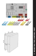
Moun
�
ng
the
Control
Housing
Fig
5.
Moun
�
ng
loca
�
ons
Fig
6.
Stress
relief
connector
1.
Locate
the
stress
relieving
cord
‐
grip.
2.
A
�
ach
connec
�
ng
nut
(F)
to
grip
body
(G).
Tighten
securely
using
nger
pressure
only.
3.
Slip
compression
nut
(H)
over
a
length
of
18/3
(18
Gauge,
3
strand)
motor
wire
and
thread
wire
through
the
assembled
cord
‐
grip.
4.
Tighten
the
compression
nut
(H)
with
nger
pressure
only.
5.
Refer
to
“Master
Wiring
Diagram”
to
wire
the
motor
to
the
LIBRA
‐
UL
‐
R
control
panel.
6.
For
basic
programming
see
“General
Programming.”
For
advanced
parameters,
please
see
the
BFT
“LIBRA
‐
UL
‐
R
Installa
�
on and User’s Manual”
Wiring
the
Motor
F
G
H
WIRE
USE
min
18/3
wire*
connec
�
ng
motors
to
control
panel
min
22/4
wire
connec
�
ng
RX
photoeye
to
control
panel
min
22/2
wire
connec
�
ng
TX
photoeye
to
control
panel
*Use stranded wire. Increase gauge if motors more than 20’ from panel
TM
Franklin Autoswing Installation Manual
© 2012 Copyright Real Carriage Door Company, Inc
11
8.
Manually release the operator (See “Manual Operation Mode”)
9.
Open the door to the desired ‘fully open’ point (approx 105 degrees is
recommended). With a measuring tape, mark the centerline of the door
mounting bracket at 40” from the center of the shaft (fig. 2). Making sure that
the arm is level, Mount the arm to the door with #14 x 1-1/2” pan head screws
(not supplied)
10.
Check clearance and movement by swinging door slowly.
11.
Relock the motor (take out of manual release mode).
12.
Repeat these steps for the other leaf, if installed.
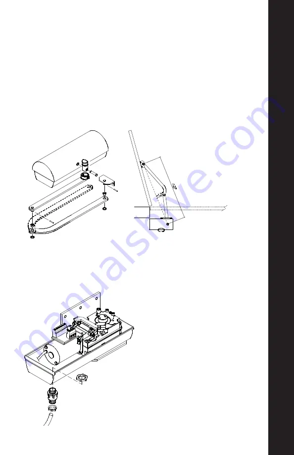
6.
Assemble
the
ar
�
culated
lever
arm
and
door
coupling
as
shown
in
g.
1.
Connect
straight
arm
and
door
coupling
to
curved
arm
using
plas
�
c
sleeve
(K)
and
washer
(L).
Secure
together
with
rolled
pin
(M).
The
dashed
arm
indicates
the
setup
for
the
right
motor
(viewed
from
inside).
7.
Slide
the
assembled
arm
onto
the
transmission
sha
�
at
the
base
of
the
motor,
and
fasten
it
using
the
long
pin
(N)
and
C
‐
ring
(O).
8.
Manually
release
the
operator
(See
“Manual
Opera
�
on
Mode”).
9.
Open
the
door
to
the
desired
‘fully
open’
point
(approx
105
degrees
is
recommended).
With
a
measuring
tape,
mark
the
centerline
of
the
door
moun
�
ng
bracket
at
40”
from
the
center
of
the
sha
�
(
g.
2).
Making
sure
that
the
arm
is
level,
Mount
the
arm
to
the
door
with
#14
x
1
‐
1/2”
pan
head
screws
(not
supplied)
10.
Check
clearance
and
movement
by
swinging
door
slowly.
11.
Relock
the
motor
(take
out
of
manual
release
mode).
12.
Repeat
these
steps
for
the
other
leaf,
if
installed.
Installa
�
on
of
Motor
(Con
�
nued)
Fig
1.
Arm
Assembly
Fig
2.
Arm
posi
�
oning
K
L
M
N
O
NOTE:
1.5” is minimum allowable arm
bend. Distances over 1.5” are
acceptable.
TM
Franklin Autoswing Installation Manual
© 2012 Copyright Real Carriage Door Company, Inc
9
WIRING THE MOTOR
1.
Locate the stress relieving cord-grip.
2.
Attach connecting nut (F) to grip
body (G). Tighten securely using finger
pressure only.
3.
Slip compression nut (H) over a
length of 16/3 (16 Gauge, 3 strand)
motor wire and thread wire through
the assembled cord-grip.
4.
Tighten the compression nut (H) with
finger pressure only.
5.
Refer to “Master Wiring Diagram”
to wire the motor to the LIBRA-UL-R
control panel.
6.
For basic programming see “Gen-
eral Programming.” For advanced
parameters, please see the BFT
“LIBRA-UL-R Installation and User’s
Manual”
4 MO
T
OR INS
T
ALLA
TION


