EMERGENCY WARNING-SYSTEM
6
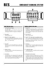
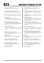
Posizione degli switch: su = OFF giù = ON
Posizione switch di tolleranza impedenza: su = 10%
giù = 20%
10. Connessioni di emergenza microfono da tavolo 1 e 2
La stazione microfonica 1 ha la priorità sulla stazione mi-
crofonica 2
11.Controllo di volume per la stazione microfonica digi-
tale VLM-105
12. Interfaccia RS232
Interfaccia di collegamento al PC per stampare l’elenco
degli errori. E’ necessario il software reperibile nella ho-
mepage del sito RCS.
.
13. Uscita relè di contatto “Emergenza” A+B
I relè di emergenza si attivano durante l’arttivazione
dei microfoni d’emergenza oppure con l’attivazione
dell’allarme.
14. Uscita relè di contatto “Errore”
Il relè errore sarà attivato qualora vi fossa un’errore del
sistema ed e possibile trasformarlo in un segnale di at-
tenzione.
15. Uscita relè di contatto “Guasto di alimentazione”
Se si verifica un guasto di alimentazione questo contatto
sarà attivato fino a quando l’alimentazione non sarà rista-
bilita.
16. Annunci 1 – 4
Monitoraggio circuito d’ingresso per l’attivazione
dell’allarme e del testo.
17. Pannello cieco per l’interfaccia digitale RR-10
Per connettere la stazione microfonica digitale VLM-
105.
18. Ingresso alimentazione di emergenza DC 24V
In caso di utilizzo dell’ ESP-300 A collegare direttamente
la linea di alimentazione 24V DC.
19. Alimentazione 230
Switch position: top=off bottom= on
Impedance tolerance: top=10% bottom= 20%
10. Connection Emergency Desk-Micro 1 and 2
The microphone station 1 has priority before station 2.
11. Volume Control for digital microphone station VLM-105
12. RS-232 Interface
For connection to the PC to print an error list.
You will find the necessary software on the RCS homepage.
13. Output Relay Contact “Emergency” A+B
The equivalent relays tighten during the application of the
emergency desk micro and also if activating the alarm
input.
14. Output Relay Contact „Error“
This contact will be activated if there is a system error,
and therefore the possibility to switch for attention
signal.
15. Output Relay Contact “Power Failure”
If there is a power failure, this contact is switched until
the power is re-established.
16. Announcements 1-4
Monitored circuit input for text and alarm activation.
17. Blank Panel for digital Interface RR-10
(for connection digital microphone VLM-105)
18. Input 24V DC Emergency Power Supply
When using the ESP-300 A – please connect to “unswit-
ched out” on the 24 V output.
19. Input Power Supply 230 V


