background image

ESC-006 A

7

PROCEDURA DI INSTALLAZIONE

Per  prima  cosa  attivare  la  centrale  di  controllo  VARES 
ESC-006 A

Tutti  i  dispositivi  e  tensioni  di  funzionamente,  che  devono 
essere controllate dal centro di controllo VARES ESC-006° 
dovrebbero essere attivati.

L’attivazione interessa solitamente i seguenti componenti:
•  Amplificatore in linea 100V (massimo 6 pezzi)
•  Amplificatore di backup
•  Stazione dei vigili del fuoco ESM-100D (massimo 2 pezzi)
•  Ingresso 1-4 di allarme
•  Voltaggio del sistema a 230V AC
•  Alimentazione di emergenza 24V DC

Prego prestare attenzione a quanto segue:

I comandi del volume sugli amplificatori collegati devono es-
sere al massimo. La regolazione del volume è fatta dal ESC-
006 A.

Se di fatto durante l’installazione della linea dell’altoparlante 
si  ha  una  registrazione  con  meno  di  20  _  sarà  misurata. 
Questo errore sarà indicato. L’errore deve essere riparato e 
l’installazione deve essere nuovamente iniziata.
Se il VLM-105, che non è monitorato è installato in aggiunta, 
l’unità RR-10 dell’evacuazione deve essere anch’essa instal-
lata.

Quando,  ordinate  ESC-006  A  e  il  VLM-105  insieme, 
l’interfaccia sarà inserita nella consegna.

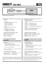
INIZIO PROCEDURA DI INSTALLAZIONE

1.  Premere “T1” una volta

2.  Premere  “RESET”  tre  volte  per  attivare  l’accesso  al 

sistema

3.  3 Premere “T1” per selezionare system

4.  4 Premere “T2” per iniziare l’installazione

Tutti i componenti sono visualizzati successivamente sul dis-
play. Dopo che l’installazione sarà completata, tutti i compo-
nenti saranno continuamente controllati.

INSTALLATION PROCEDURE

Please activate as a first step the Control Center ESC-
006 A.

All devices and operating voltages,  which are to be cont-
rolled  by  the  VARES  Control  Center  ESC-006  A  should  be 
activated.

It usually concerns the following components:
•  100 V amplifier (max. 6 pcs.)
•  Backup amplifier
•  Fire-Brigade Station (max. 2 pcs.)
•   Input alarm message 1-4
•  System voltage 230 V AC
•  Emergency power 24 V  DC

Please note as follows:

The  volume  controls  on  the  connected  amplifiers    have  to 
be adjusted to full volume. The volume regulation is done by 
the ESC-006 A.

If done during the installation of the loudspeaker line  an ad-
justment with less than 20 

 is measured. This error will be 

indicated.  The  error  has  to  be  deleted  and  the  installation 
must be started again. 

If the VLM-105 which is not monitored is installed additional-
ly, the evacuation unit RR-10 has to be installed too. When 
ordering both products ESC-006 A and VLM-105 together, 
the interface will be assembled in the scope of delivery.


START OF THE INSTALLATION PROCEDURE

1.  Push „T1“

2.  Push „RESET“ 3 times


to activate the access

3.  Push “T1”


To select “System”

4.  Push „T2“


the installation starts ...

All components  are successively visual on the display. After 
the installation is completed, all components will be conti-
nuously checked.

Summary of Contents for VARES ESC-006 A

Page 1: ... ENGLISH DEUTSCH SISTEMA SONORO DI EVACUAZIONE ELECTROACOUSTIC EMERGENCY WARNING SYSTEM INTRODUZIONE OPERATING INSTRUCTIONS VDE 0828 DIN EN 60849 IEC 60849 ...

Page 2: ...enzione l unità per vedere se ci sono dan ni dovuti al trasporto Ogni prodotto RCS è controllato con attenzione dalla fabbrica ed è imballato in una scatola spe ciale per un trasporto sicuro Informare immediatamente il corriere se osservate il danneggiamento della scatola o del prodotto dovuti al trasporto Reso Imballate l unità nella scatola ed attendete il controllo da parte del corriere Informa...

Page 3: ...ntazione di emergenza La voce digitale in memoria contiene un testo per evacu azione e una sirena In caso di necessità messaggi di av viso speciali possono essere programmati singolarmente dall installatore INTRODUCTION In the case of an alarm an electroacoustic emergency war ning system may avoid panic by understandable speaker an nouncements which are contrary to the howling of a siren a much mo...

Page 4: ...ere attivata led verde o disattivata dai pulsanti di comando 1 6 La selezione di zona e tutte le chiamate degli ESM 100 D non sono effettuate dai pulsanti di comando I VLM 105 e l ESM 100D non sono controllati dai pulsanti di cont rollo FRONT PANEL ESC 006 A 1 LCD Liquid Crystal Display The clear 20 digit 2 lines display inform constantly about the system status During the configuration the individ...

Page 5: ...r esempio un interruttore a tempo 9 DIP switch 1 4 Switch 1 pre chime per VLM 105 on off Switch 2 inserimento disinserimento impedenza on off Switch 3 tolleranza d impedenza del 10 o 20 Switch4 inserimento disinserimentodellamessaaterra REAR PANEL ESC 006 A 1 Input Speaker Lines 1 6 Please note that the 100V cable must be connected co ming from the amplifier 2 Output Speaker Lines 1 6 100 V output ...

Page 6: ...le RR 10 Per connettere la stazione microfonica digitale VLM 105 18 Ingresso alimentazione di emergenza DC 24V In caso di utilizzo dell ESP 300 A collegare direttamente la linea di alimentazione 24V DC 19 Alimentazione 230 Switch position top off bottom on Impedance tolerance top 10 bottom 20 10 Connection Emergency Desk Micro 1 and 2 The microphone station 1 has priority before station 2 11 Volum...

Page 7: ...system 4 4 Premere T2 per iniziare l installazione Tutti i componenti sono visualizzati successivamente sul dis play Dopo che l installazione sarà completata tutti i compo nenti saranno continuamente controllati INSTALLATION PROCEDURE Please activate as a first step the Control Center ESC 006 A All devices and operating voltages which are to be cont rolled by the VARES Control Center ESC 006 A shou...

Page 8: ...ssaggio 1 Input 2 Messaggio 2 Input 3 Messaggio 3 Input 4 Messaggio 4 I seguenti messagi sono pre memoirzzati Messaggio 1 messagio di evacuazione Messaggio 2 sirena DIN DIN 33404 Messaggio 3 4 toni chime Messaggio 4 4 toni chime Westminster PROGRAMMING Only authorized persons should program the system Changes or false inputs can affect the security a ADJUSTMENT OF THE EVACUATION SIGNAL VOLUME Push...

Page 9: ... indicante il sistema di cari ca a contatto di rottura della linea monitor sistema alimen tazione di emergenza entrambi come contatti normalmente aperti può essere registrato simultaneamente schema del punto b1 indicatore di ingresso 0V Melder indicator 1 4 VARES 4K7 4K7 b2 Programming of attention signals bevor emergency massages Push T1 Push RESET 3 times to activate the access Push T1 to select...

Page 10: ...sage Start MESSAGIO 1 MESSAGIO 2 MESSAGIO 3 MESSAGIO 4 T1 T1 T1 T1 T1 S 1 S 2 S 3 S 4 T1 T1 T1 T1 assegnare l annunciatore assign the annunciator START attivare l annunciatore activate the annunciator RESET rimuovere il menu attivo exit active menu item RESET SISTEMA T1 T2 SEGNALE INTERRUTTORE SPECIALE inizio dell installazione installation running T2 T1 VOL VOL ...

Page 11: ...ator capacity 27 Ah BA 052 42 Ah BA 080 Dimensions WxHxD 483 x 133 x 350 mm 3 HE Weight 11 6 kg ACCESSORIES VARES SYSTEM ACCESSORIES EMERGENCY POWER SUPPLY ESP 300 A The emergency power supply ESP 300 A is designed for the connection of up to 6 power amplifiers 120 W as well as an additional backup amplifier The power amplifiers stages of the same quantity but with a higher capacity are used both the...

Page 12: ...F 4dBu 4dBu 20 AC 230V 50Hz 650W SERIAL NO 400Hz PROGRAM PRIORITY leak 10 CONTROL LEVEL INPUT INPUT 24V FUSE INSIDE BALANCED OUTPUTS RMS 240W W MONITOR 100V 42 2 6 70V 44V 8 COM 25V P A POWER AMPLIFIER MADE IN KOREA CAUTION RISK OF ELECTRIC SHOCK DO NOT OPEN MODEL NO BA 240CP EQUIPMENT TO RAIN OR MOISTURE OR ELECTRIC SHOCK DON T EXPOSE THIS TO REDUCE THE RISK OF FIRE WARNING DC POWER 24V 40A ON OF...

Page 13: ...000 Hz Directivity Niere Impedance 1200 Ohm Selctivity 78dB 3dB Keyboard linie 1 5 und all call Dimensions WxHxD 220 x 53 x 165 mm gooseneck 290 mm Weight ca 1250 g VARES SYSTEM ACCESSORIES FIRE BRIGADE CALL STATION ESM 100 D The fire brigade call station ESM 100 D is monitored compli ant to VDE0828 EN60849 The microphone capsule and the talk button are continuous ly for function and via checked me...

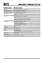
Page 14: ... 100V 4x supervised switching inputs for text or alarm activation Input 4 has a special function to analyse external errors Switching outputs 2x Emergency break or open contact 1x Error break or open contact 1x Power failure break or open contact all max 120V max 2A PC interface RS 232 Voice memory Eprom max 240 sec Display 2 line Display LEDs Control panel 4 programming buttons 6 buttons and cont...

Page 15: ...sbilanciate musica e segnale esterno 7 x 100 V 4x ingressi sorvegliati per attivazione segnale di allarme Usicta Switching 2x Emergency contatti a rottura aperti 1x Errore contatti a rottura aperti 1x Problemi di alimentazione contatti a rottura aperti Tutto massimo 120V massimo 2 Interfaccia PC RS 232 Memoria messaggi Eprom massimo 240 secondi Display 2 linee a Led Pannello di controllo 4 tasti d...

Page 16: ... data only allowed with our strict permission Veröffentlichung und Vervielfältigung der enthaltenen Daten auch auszugsweise nur mit unserer ausdrücklichen Genehmigung Hardware and Software specifications subject to change without notice Techische Änderungen in Hardware und Software vorbehalten RCS23 07 2007 ...

Reviews: