


48
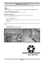
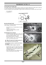
MAIN BRUSH “2/2” (FIG.11)
Cleaning the dust guide plate
If the motor sweeper is used outdoors (courtyards, squares, etc.) where the ground may be damp, dirt may build up
on the front part of the main brush dust guide plate, reducing the effi
ciency of the machine.
Check the condition of the dust guide plate at regular intervals and remove any encrusted dirt with a metal scraper.
•
Dust guide plate 1.
•
Encrusted dirt 2.
1
2
Removal of main brush
The main brush can be removed from the left side of the
motor sweeper in the following way:
•
Open the main brush inspection door 3 using the
closing 4.
•
Loosen the fi xing screws 5.
•
Slide the drive roller and lever unit 6 off .
•
Slide the brush 7 off .
Positioning the main brush
•
Insert the main brush, centering the notches with
the fi ns on the right side of the drive motor sup-
port. (See positioning direction - “A-B”).
•
Place unit 6 on the brush 7 and lever 8.
•
Tighten the butterfl y screw 5 until the drive sup-
port 9 is positioned inside the brush.
N.B.: When the main brush is being positioned, it
has to be done in the correct direction.
A = Positioning direction on the left side of the mo-
tor sweeper.
B = Direction of motor sweeper in operation.
• After
fi tting the new brush, repeat the adjustment
operations described, moving the stopper on the
slotted element in the opposite direction to that
described for adjustment.
•
Return the mobile barrier on the Refuse container
inlet to the initial position (fully raised).
3
4
7
8
5
5
6
9
B
A
Summary of Contents for 31.00.127
Page 2: ...2 ...
Page 3: ...3 ITALIANO Pagina 4 ENGLISH Page 32 FRANÇAIS Page 61 NEDERLANDS Pagina 90 ...
Page 27: ...27 SCHEMA IMPIANTO ELETTRICO FIG 20 15 N1 P codice schema 1 9 12044 ...
Page 32: ...32 ENGLISH ...
Page 56: ...56 WIRING DIAGRAM FIG 20 15 N1 P codice schema 1 9 12044 ...
Page 61: ...61 FRANÇAIS ...
Page 85: ...85 SCHÉMA DE CÂBLAGE FIG 20 15 N1 P codice schema 1 9 12044 ...
Page 90: ...90 NEDERLANDS ...
Page 114: ...114 SCHEMA ELEKTRISCH SYSTEEM FIG 20 15 N1 P codice schema 1 9 12044 ...


