49
ENGLISH
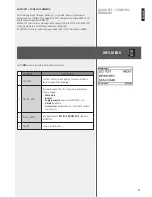
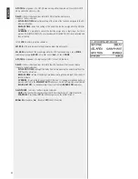
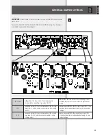
JP1 to JP8
AB
position: the two resistors for monitoring are
inserted in the respective logic output (GPO).
BC
position: the two resistors for monitoring are not
inserted (‘dry contact’) in the respective logic output
(GPO).
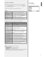
JP 9
Jumper inserted (ON): normal operation of the first logic
input (GPI 1), which can be connected to a dry closing
contact.
Jumper removed (OFF): the first logic input (GPI 1) can
be linked to an external device having its own output
voltage.
JP 10
Jumper inserted (ON): normal operation of the second
logic input (GPI 2), which can be connected to a dry
closing contact.
Jumper removed (OFF): the second logic input (GPI
2) can be linked to an external device having its own
output voltage.
IMPORTANT:
iNTerNal
juMper
SeTTiNg
Shall
be
carried
OuT
ONlY
bY
eiTher
rcf
Or
aN
auThOriSed
SerVice
ceNTre
.
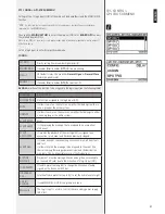
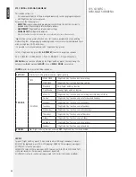
Remove the lid and look at the back GPI / GPO board (in this drawing, the 10 jumpers
are marked in grey inside the rectangle):
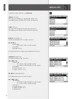
INTERNAL JUMPER SETTINGS
ZOOM:
Summary of Contents for MX 9502
Page 2: ......

