


PART I—SERVICE DATA
(1) RADIOTRON SEQUENCE
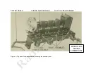
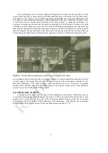
Figure 3 illustrates the sequence of the Radiotrons in the receiver proper, omitting Radiotron UX-
280 in the socket power unit. From right to left, when facing the front of the Radiola, the Radiotron
sequence is as follows:
Radiotron No. 1 is an untuned stage of radio frequency amplification. It is coupled directly to the
antenna and ground and is not tuned in any way.
Radiotron No. 2 is a stage of tuned R. F. amplification employing a grid resistance to prevent
oscillation. It is tuned by the first gang condenser.
Radiotron No. 3 is the second stage of tuned E. F. amplification. It also
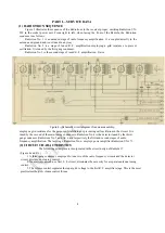
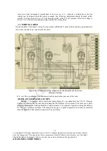
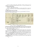
Figure
4
—
Schematic circuit diagram of receiver assembly.
employs a grid resistance for the purpose of stabilizing or preventing self oscillation in the circuit. It is
tuned by the second of the main tuning condensers. Radiotron No. 4 is the detector tuned by the third-
gang condenser. Radiotrons No. 5 and No. 6 are respectively the first and second stages of audio
frequency amplification. The last stage, Radiotron No. 6, employs power amplifier Radiotron UX-171.
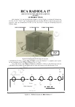
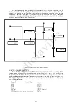
(2) CIRCUIT CHARACTERISTICS
The following principles are incorporated in the circuit design of Radiola 17
(Figure 4 and 4A.)
1. A three-gang condenser, employed to tune two of the radio frequency circuits and the detector
circuit, provides one tuning control.
2. An aperiodic antenna, or first E. F. circuit, eliminates the necessity for a separate antenna tuning
control.
3. The volume control regulates the input grid voltage to the first R. F. amplifier stage. This is the most
practical method of volume control for use
6


