


Radiotron UX-171 potentiometer. This connection is 30 "C". The action of this arrangement
is somewhat different from the method used for obtaining the —9 volts "C" for the UX-226 Radiotrons.
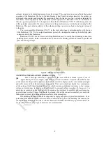
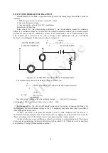
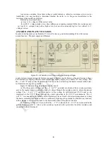
In obtaining the —9 volt "C" potential for the Radiotron UX-226, the voltage drop across a
portion of the resistance strip (see A to 0, Figure 18) is used for this potential. Any point on the strip
from any other point is either positive or negative depending on "whether the other point is toward the
positive side "A" or the negative side "C". For example point "B" would be negative in regards to point
"A" and positive in regards to point "C". Now using this same principle, but taking the current now
from "A" to "C" through the plate and filament of Radiotron UX-171 and the resistance in series with
the center connection to the potentiometer we may find either a positive or negative drop depending on
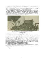
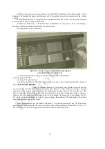
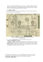
Figure
19—
Removing the receiver assembly from the cabinet.
where the point of connection is made. By connecting point "D" (Figure 18), as a source of positive
potential any point toward " C " will have an increasingly negative potential. The value of this negative
potential will depend on the resistance connected between "C" and "D". In Radiola 17 this negative
potential is 30 volts and, as shown, gives the proper bias for Radiotron UX-171.
This parallel circuit across the resistance isolates the "C"
potential
for Radiotron UX-171 from
the plate and "C" voltages for the other Radiotrons. Doing this keeps fluctuations in the various plate
supplies from varying the "C" potential on this tube. More stable operation and less distortion is the net
result.
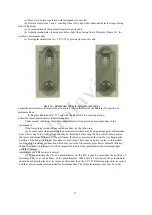
(26) HEATING OF
CABINET
Under normal conditions when the lid of Radiola 17 is closed the interior parts in the vicinity of
Radiotron UX-280 will become quite warm. This is a normal condition. It keeps all the mechanism dry
and maintains maximum operating efficiency even under severe climatic conditions.
22


