


cases give better loudspeaker reproduction. If however an A. C. voltmeter is obtainable or the line
voltage can be obtained from the power company -the following adjustment should be made at this
switch:—For lines from 105 to 115 volts keep the switch at the 110-volt position. If the line voltage is
from 115 to 125 the switch should be placed at the 120-volt position.
(21)
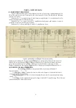
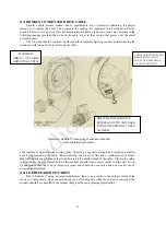
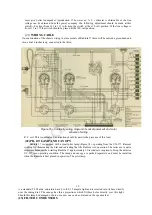
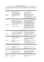
WIRING CABLE
On examination of the chassis wiring in some models of Radiola 17 there will be noticed a green dead end
wire, about 6 inches long, connected to the third
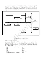
Figure
16
—
Continuity wiring diagram of socket power wit and color
scheme of wiring.
R. F. coil. This is normal and no attention should be paid to the presence of this lead.
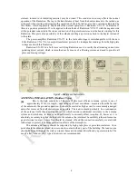
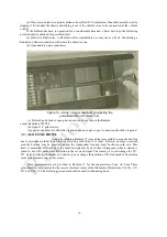
(22) PILOT LAMP AND CANOPY
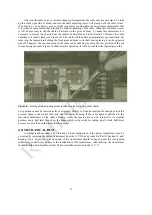
Radiola 17 is equipped with a small pilot lamp (Figure 14), operating from the UX-171 filament
winding for illuminating the dial and indicating that the Radiola is in operation. The latter use is quite
important because when starting Radiola 17 approximately 30 seconds are required to bring the detector
UY-227 into operating condition. The lamp and canopy are packed separately and must be installed
when the Radiola is first placed in operation. The pilot lamp
19
is a standard T-3 Mazda, miniature base, 6 volt, 0.15 ampere light and is screwed into its base directly
over the tuning dial. The canopy has three projections which fit three holes directly over this light.
Should this lamp be damaged or burn out a new one can be obtained on the open market.
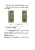
(23) FILTER CONDENSERS


