


8. Connect power cable from Socket Power Unit and test Radiola.
If R
adiola is in correct
operating condition return chassis assembly to cabinet in reverse order of that used to remove it.
(6) REPLACING AUDIO TRANSFORMERS
The audio transformers of Radiola 17 are built together as a unit. In making a replacement the
following procedure should be used:
1. Remove receiver chassis from cabinet as described in Part
II,
Section 1.
2. Remove output transformer from chassis by removing four screws holding it in place.
3. Unsolder and tag all leads.
4. Remove transformer assembly by turning up tabs holding it to chassis
frame with screw driver.
5. Under the old transformer, between the chassis frame and the transformer is located a piece of
insulating paper. This must be replaced to its normal position as there is a possibility of grounding the
core of the transformers to the frame of the chassis unless it is in place.
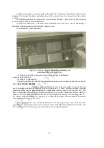
6. Place the new transformer assembly in position occupied by the old and fasten to frame by
bending over metal tabs that hold it in place.
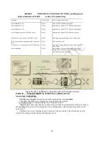
7. Solder all leads in place as indicated by tags attached. The correct connections are shown in
Figure 22.
8. Replace receiver 'chassis assembly in cabinet in the reverse order of
that used to remove it.
(7) REPLACING OUTPUT TRANSFORMER
The output transformer of Radiola 17 is held in place by means of four tabs which hold the output
transformer to the vertical part of the chassis frame. A step by step procedure for replacing this unit is
as follows:
1. Remove receiver chassis assembly from cabinet as described in Part
II,
Section 1.
2. Unsolder and tag the four leads connecting the output transformer.
3. Bend up the four tabs that hold the output transformer to the vertical
frame
4. The transformer may now be removed and the new one placed in the position occupied by the
old one. The tabs should be bent over to fasten the
transformer to the frame.
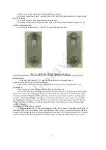
5. Push the four leads from the transformer through the frame and connect them as indicated by
tags previously attached to proper connection. These
connections are shown in Figure 23.
6. Return receiver assembly to cabinet in reverse order of that used to
remove it.
(8) REPLACING CONDENSER DRIVE CABLE
The condenser drive cable of Radiola 17 is made of phosphor bronze and is very rugged. If
replacement becomes necessary proceed as follows: ^
1. Remove receiver chassis assembly from cabinet as described in Part
II,
Section 1. Place
chassis on table in normal position with controls to the front.
2. Release the cable adjusting screw and clamp, and remove old cable from large drum and
grooved drums completely.
28


