TC3 “O” V2
RC Product Designs
Page 12
Ø
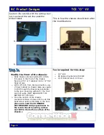
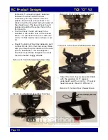
Install the stock rear chassis braces to the
gearbox with the original screws.
Ø
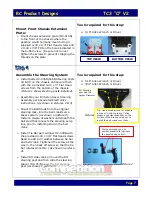
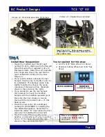
Install the Rear Shock Tower mount with
the 0.20” spacer using 3 4-40 x ½” Socket
Head screws and 1 4-40 x 5/8” socket
head screws on the hole that uses the
spacer.
Ø
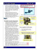
Install ball studs in the shock tower and
secure them with nuts. Install shock tower
to shock mount with the 2 supplied 4-40 x
1/2” button head screws and 1 4-40x3/8”
button head screw in the center of the
mount. Secure those with the Nylock Nuts
provided.
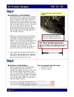
(Example of installation can be
seen in picture on the right.)
Ø
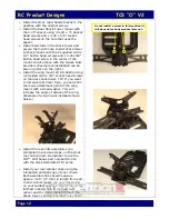
Install the wing mount kit DC-A4222 using
4 provided 4-40 x 3/8” socket head screws
on the rear shock tower. TIP: If you want
to increase rear down force, you can shim
the lower attachment point of the wing
mount with a small washer. This will
increase the angle of attack of the wing.
(Example of wing mount installed shown
below.)
Ø
Install the rear CVD assemblies you
completed in previous steps, on the stock
rear hub carriers. Remember to use the
MIP™ CVD bones part number DC-012
with the stock Associated TC3 axles.
Ø
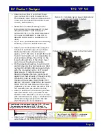
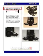
Install your rear camber links using the
turnbuckle and ball cups of your choice.
Each assemble link should measure
approx. 3.05” (77 mm) in length from end
to end. Actual length will vary depending
on your camber settings. Mount link on the
furthest inboard hole in the rear hub
carrier and the upper inboard hole in the
shock tower.
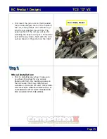
(Example camber link shown
Do not install a screw in this location (it
will be used for body mounts later on).


