Page 11
TC3 “O” V2
RC Product Designs
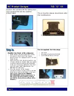
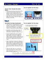
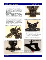
Picture 12: Front End Assembly Front View
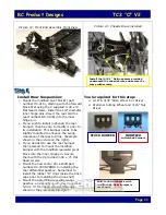
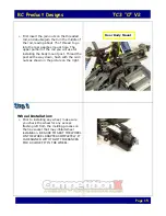
Picture 14: Chassis Brace installed
Install Rear Suspension:
Ø
Mount the modified pivot blocks (part
number DC-016), starting with the forward
block first using the 2 supplied 4-40 x ½”
Flat Head screws. Install the 1/8” diameter
inner hinge pins. Insert the rear A-Arms
(part number DC-014B) into the inner
hinge pin.
Ø
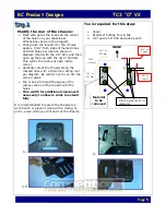
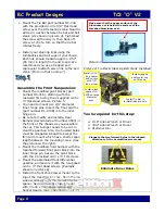
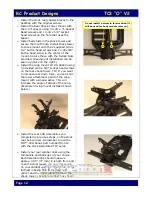
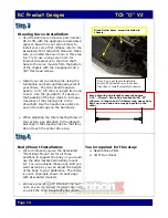
If you wish to install (optional) the rear
bumper, then be sure to modify it prior to
its installation. This bumper needs to be
slightly modified to enhance the swing
clearance of the rear A-Arms.
(Example
shown in the picture on the right).
Ø
If you decided to use the rear bumper
then proceed to mount the modified
bumper with the modified rearward pivot
block into the inner hinge pin. Secure
them with the 2 provided 4-40 x ½” Flat
Head screws.
Ø
Mount the new center drive shaft part
number DC-003B PRIOR to installing the
rear differential gearbox. Remember to
install the rubber “O” rings inside the drive
cups prior to installing the drive shaft.
Ø
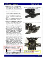
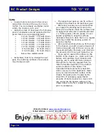
Mount the assembled rear differential
gearbox, and secure it with the 4 supplied
4-40 x ½” Flat Head screws.
(Example
shown in the picture on the right).
Tools required for this step:
Ø
0.16” & 3/32 “Allen Wrench or Driver
Ø
Dremmel Cutting Wheel and 3/16” Nut
Driver
STOCK BUMPER
MODIFIED
w/Notched Corners
Install the (4) 0.1” Delrin spacers provided
underneath the chassis brace and secure the
brace with screws.
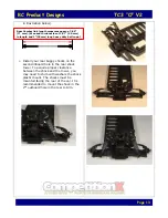
Bottom view of chassis with
modification. Rear bumper is
not shown.


