background image

TC3 “O” V2

RC Product Designs

Page 2

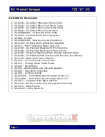
DC-000B V2 Kit Content:


DC-001B – V2 Carbon Fiber Rear Shock Tower 


DC-002B – V2 Carbon Fiber Front Shock Tower


DC-003B – V2 Carbon Fiber Center Drive Shaft


DC-004B – V2 Carbon Fiber Chassis Brace


DC-005B/006B – V2 Brass Steering Posts


DC-007B – V2 Black Delrin Steering Spacer


DC-008 - Tie Bar


DC-009B/010B - Steering Knuckle Extensions


DC-011B – V2 Black Delrin Wheel Hex Adapters


DC-012 – MIP™ CVD Steel Bones (Set of 4)


DC-013B – V2 Machined Black Delrin Front A-Arms


DC-014B – V2 Machined Black Delrin Rear A-Arms


DC-015B – V2 Nylon Reinforced Front Chassis Extension Plate


DC-016B – V2 Modified Front and Rear Arm Mounts (Pivot Blocks)


DC-017B – Black Delrin Servo Mounts


DC-018 – V2 Front Shock Tower Mount


DC-019 – V2 Rear Shock Tower Mount


DC-020 – Decal Sheet


DC-025 - Additional screws, nuts and washers


DC-026 – Steel inner hinge pins


DC-030 – V2 Body & Wing


DC-U1516D – Front White smooth design (Dish) 2.2”


DC-U1458X – Rear White smooth design (Dish) 2.2”


DC-3872 – 4 Degree Front Block Carriers


DC-9150 – B3 Servo Saver Kit (Steering Bell-Crank Kit)


DC-7319 – Body Mounts


DC-A4222 – Wing Mount Kit
Summary of Contents for TC3-O V2

Page 1: ...C3 O V2 RC Product Designs Instruction Manual TC3 O V2 4WD Off Road Buggy Conversion Kit for the Associated TC3 Kit DC 000B Website Address www rcproductdesigns com E Mail Address rcproductdesigns com...

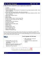
Page 2: ...13B V2 Machined Black Delrin Front A Arms DC 014B V2 Machined Black Delrin Rear A Arms DC 015B V2 Nylon Reinforced Front Chassis Extension Plate DC 016B V2 Modified Front and Rear Arm Mounts Pivot Blo...

Page 3: ...need to complete the kit R C 2 channel surface frequency radio system Battery pack 6 cell Electronic speed control R C electric motor Pinion gear size to be determined by type and wind of motor you w...

Page 4: ...uckles All Ball Studs and Ball Cups Motor Cam Motor Clamp Steering Servo Horn Servo Offset Spacers Rear Chassis Braces Antenna Tube and Cap We have designed the TC3 O to utilize as many of the stock T...

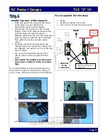
Page 5: ...s along the marked lines with a Dremmel cutting tool per diagram Be careful not to cut into the corner radius File or sand to blend the edges of the cutout section of the chassis with the holes Trim w...

Page 6: ...ll from the top direction use 2 holes marked on chassis plate as a guide to drill through the chassis perpendicular to the new mounting surface for the front A Arm Mounts NOT SQUARE TO THE BOTTOM OF T...

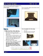
Page 7: ...rack into the bell crank servo saver system As shown in picture 4 Install a couple of washers underneath the ball stud that connects the steering servo link prior to installing stud in the bell crank...

Page 8: ...the forward holes must be elongated inboard to accept the front arm mount which has a shorter span length between the mounting holes See the picture on the right Mount the modified front bumper with t...

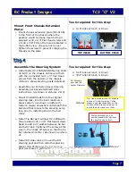
Page 9: ...rt number DC 009B 010B and secure them with the 2 provided 4 40 x 3 8 Socket Head screws If installing Aluminum Steering Knuckles then we recommend applying a small amount of thread locking compound s...

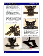
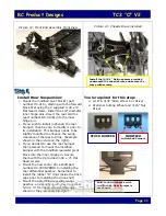
Page 10: ...e 4 40 x flat head screw as shown in pic 13 Mount the Delrin Wheel Hex Adapters part number DC 011B to the stock axles Make sure you have the pins inserted in the axle prior to installation The hex ad...

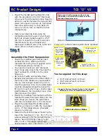
Page 11: ...he rear bumper then proceed to mount the modified bumper with the modified rearward pivot block into the inner hinge pin Secure them with the 2 provided 4 40 x Flat Head screws Mount the new center dr...

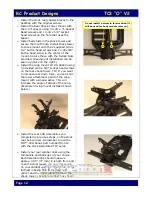
Page 12: ...rews on the rear shock tower TIP If you want to increase rear down force you can shim the lower attachment point of the wing mount with a small washer This will increase the angle of attack of the win...

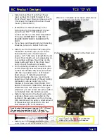
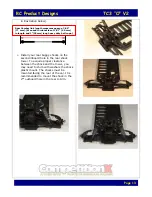
Page 13: ...rance between the shock and the tower you may need to shim with washers the shock plastic mount The shocks must be mounted facing the rear of the car It is recommended to mount the shock in the 2nd ou...

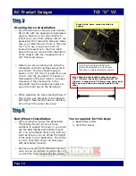
Page 14: ...When adjusting the total steering throw of the system pay attention to the inboard ball cups in the steering links so that they do not touch the center drive cup Body Mount Installation We recommend...

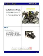
Page 15: ...ng the body mount post Thread the post all the way down flush with the 4 40 nuts as shown in the picture on the right Wheel Installation Prior to installing any wheel make sure you check the wheel for...

Page 16: ...Teflon grease Lithium grease or even powder graphite to keep the surfaces lubricated Failure to clean them on a regular basis may inhibit the steering system to operate smoothly We recommend that when...

Reviews: